
Load sharing composite shaft

Inactive Publication Date: 2008-09-23
BURKETT JERALD S
View PDF20 Cites 18 Cited by
  • Summary
  • Abstract
  • Description
  • Claims
  • Application Information

AI Technical Summary

Benefits of technology

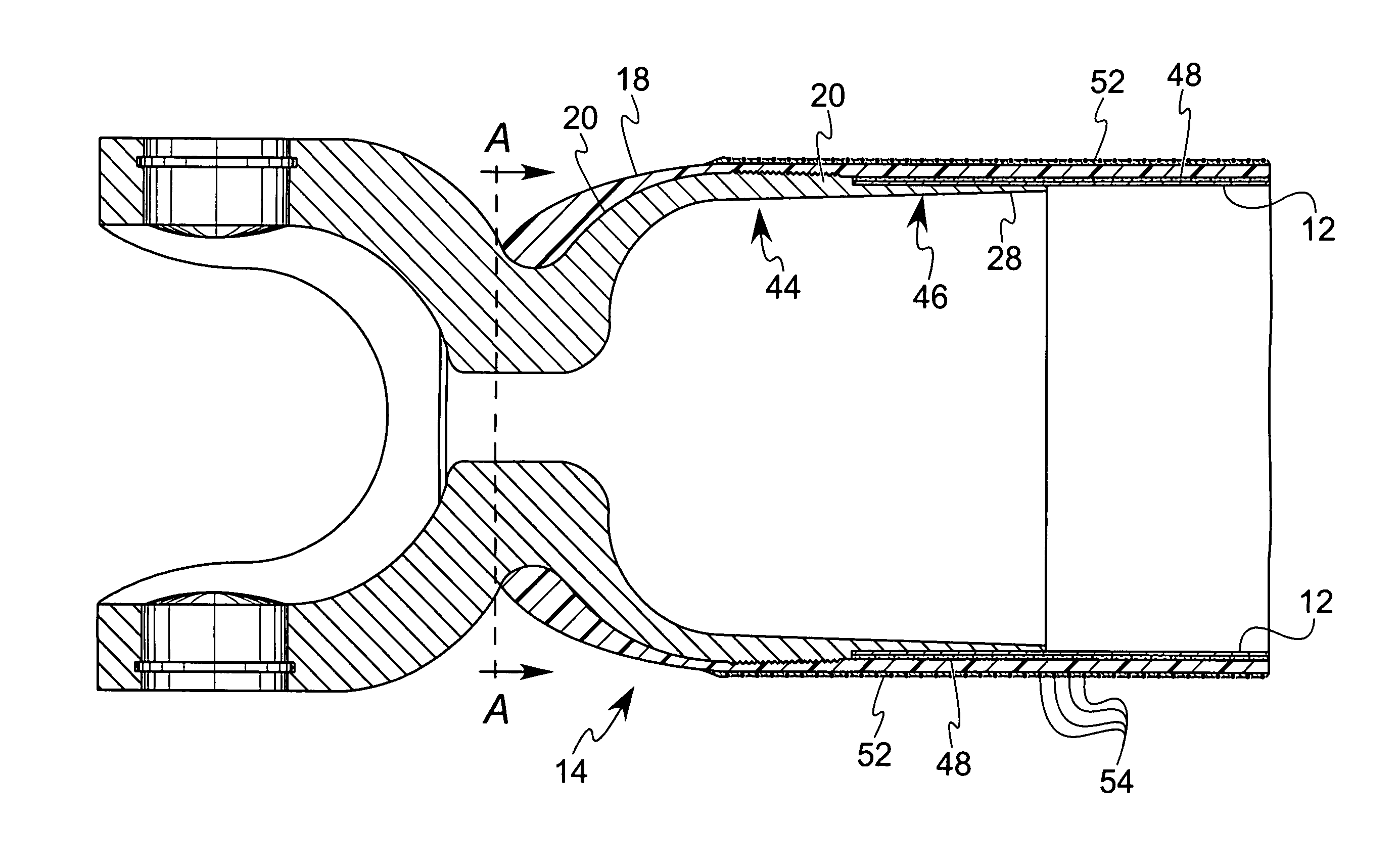
[0008]The present invention provides a composite shaft construction which provides for improved structural strength and improved cost of construction. In particular, an improved design and manufacture for a composite shaft is provided including an inner tube member for the shaft, at least one end piece located adjacent at least one end of the inner member and a composite material covering the inner tube member and at least a portion of the end piece wherein the portion of the end piece covered with the composite material defines a convexly curved area of the end piece.
[0009]In the preferred embodiment, an end piece is provided at either end of the shaft, and specified torsional loads are transferred from the end pieces effectively into the composite tube. Additionally, the inner tube typically is a thin metal tube of sufficient rigidity to act as a forming mandrel for the composite material and to hold the end pieces in alignment relative to each other during manufacture of the composite shaft structure. In contrast to prior art composite structures which rely totally on a single load path from the end piece surface through a bonding material, or adhesive, and then to the composite tube surface, the shaft structure of the present invention provides multiple mechanical load paths to transfer loads effectively from the end pieces to the composite cylindrical section.
[0012]This invention's structural advantages result in a shaft with greatly increased load transfer ability of the end pieces to the composite material whereby the durability, reliability and overall load carrying capability of the composite shaft is increased.

Problems solved by technology

However, widespread use of composite material shafts for has been extremely limited as a result of structural and economic limitations associated with the design and construction of the shafts.
Structural limitations of common practice occurs when highly loaded shaft applications are necessary.
While this practice is accepted in the aerospace industry, it creates many doubts by potential customers outside of aerospace, especially in the area of high load applications such as driveshafts.
From a structural standpoint, these composite shafts are totally dependent upon the quality and inherent characteristics of the bonding process, as well as being subject to potential human error which may be introduced during assembly and bonding of the end pieces to the composite tube.
Economic limitations associated with common practice for constructing composite shafts generally result from the high labor content of the manufacturing processes, and in particular the high labor content associated with construction of the composite tube construction, and the high labor content associated with the insertion and bonding process for attaching the metallic end pieces into the composite tube.
This metal tool is typically a high-grade steel which requires a high level surface finish resulting in a fairly expensive tool.
This tool cleaning and preparation portion of the manufacturing process requires considerable time and attention to detail which ultimately adds substantial cost to the final part.
With regard to the cost associated with insertion and bonding of the end pieces into the composite tube ends, the operations associated with this process are considered critical to the proper performance of the final product and therefore requires substantial time and attention to detail.
Failure to follow any part of this critical process may result in catastrophic part failure as a result of the end piece debonding from the composite tube.
If this does not happen, the bonding agent will not adhere to the surfaces substrate resulting in an adherend failure.
Consequently, human error plays a large roll in any failures resulting from defects in the bonding process.
Obviously, due to the criticality of this process, strict manufacturing process and quality procedures must be followed (typical of aerospace industry), which results in high labor content.
Obviously this process, while adequate for certain lightly loaded high cost applications does not lend itself to high volume production.
However, great difficulties arise in the manufacturing process due to the low mechanical properties of the foam core itself.
Alignment of end pieces and adequate strength and stiffness required for the manufacturing process limits the success of this approach, especially for long narrow shafts with high length to diameter ratios.

Method used


Image

  • Load sharing composite shaft
  • Load sharing composite shaft
  • Load sharing composite shaft

Examples


Embodiment Construction

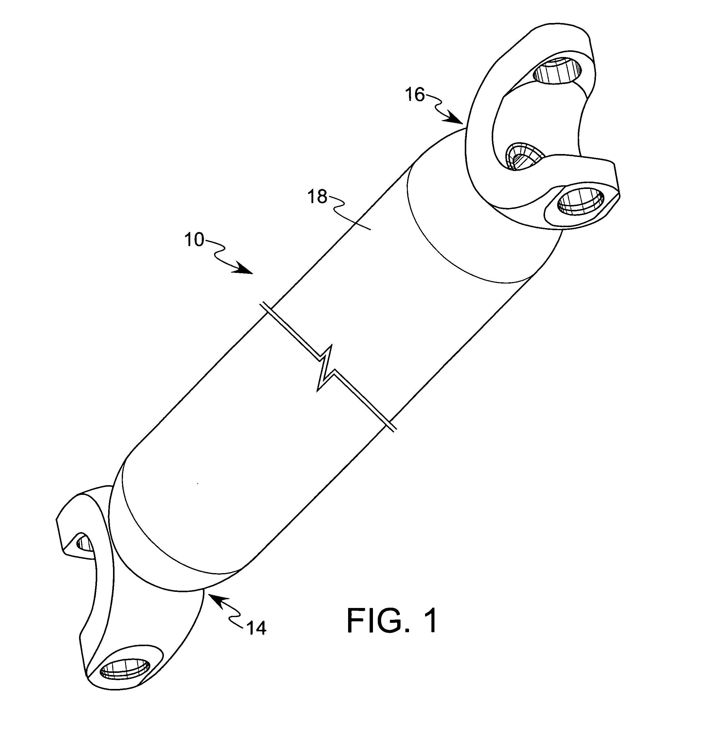
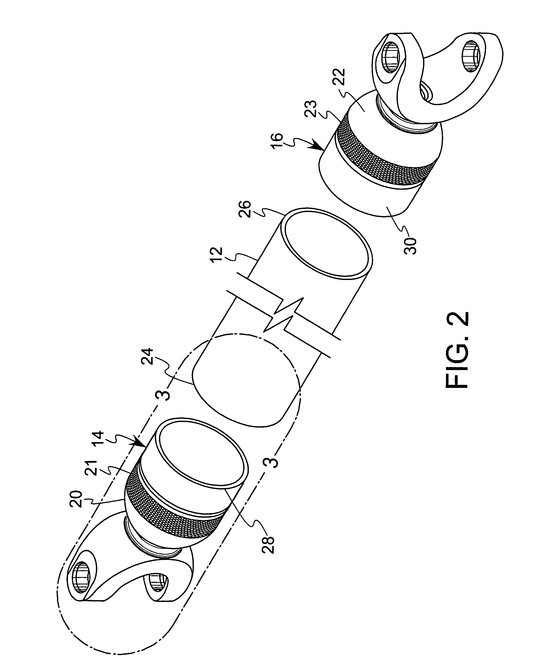
[0020]Referring to FIGS. 1–3, the composite shaft 10 of the present invention is illustrated and, as is described further below, is particularly designed for use in high speed, high torque applications, such as in use as a vehicle drive shaft.

[0021]The shaft 10 comprises an inner tube member 12, a pair of end pieces 14, 16 located at either end of the inner tube member 12, and a composite material overwrap 18 formed of resin and fibers covering the inner tube member 12 and a portion 20, 22 of each of the end pieces 14, 16, respectively. The inner tube preferably comprises a thin metal tube and defines opposing open ends 24, 26. Further, each portion 20, 22 of the end pieces 14, 16 includes a knurled surface 21, 23 which is preferably 0.015 inch deep and 0.015 inch high to facilitate formation of a mechanical connection between the composite material 18 and the end pieces 14, 16.

[0022]Each of the end pieces 14, 16 preferably is formed as a turned metal component, such as on a CNC (co...


PUM


Abstract

A composite shaft for transmitting torsional forces between end pieces of the shaft. The shaft includes an inner tube member with an end piece mounted at each end of the tube. A composite material is provided covering the inner tube member and at least a portion of the end pieces. The composite material includes elongated fibers oriented at a predetermined angle which optimizes the strength of the shaft for a desired shaft performance, and the shaft is constructed to provide multiple load paths between the end pieces.

Description

BACKGROUND OF THE INVENTION[0001]This invention relates to a cylindrical composite shaft which includes end pieces to transmit torsional forces. Currently it is well known that open ended, generally cylindrically shaped tubes formed of composite materials, such as materials comprising graphite, boron, aramid, glass fibers and epoxy, polyester and / or vinylester matrix, have extremely high strength to weight ratios. Also, depending on composite material selection, these tubes are capable of high stiffness to weight ratios and are consequently replacing metal tubes for the transmission of tensile, compression, bending and / or torsional loads. Some common applications of composite material tubular shafts are rollers in paper mills, bicycle frames, driveshafts, and golf club shafts. Composite driveshafts also have another well-known advantage over all-metal shaft constructions by providing a major reduction in noise, vibration, and harmonics. All composite materials have natural dampening...

Claims


Application Information

Patent Timeline
IPC IPC(8): F16C3/02
CPCF16C3/026F16C2326/01F16C2326/06F16D3/387
Inventor BURKETT, JERALD S.
Owner BURKETT JERALD S
Learn More