
Hybrid fuel cell system with battery capacitor energy storage system

a fuel cell and capacitor technology, applied in the field of hybrid fuel cell systems with battery capacitor energy storage systems, can solve the problems of increasing the cost of manufacturing, increasing the cost of dc/dc converters, so as to reduce the soc cycle, maintain the battery life, and reduce the soc swing

Inactive Publication Date: 2008-09-23
GM GLOBAL TECH OPERATIONS LLC
View PDF3 Cites 39 Cited by
  • Summary
  • Abstract
  • Description
  • Claims
  • Application Information

AI Technical Summary

Benefits of technology

The present invention is about a fuel cell system that uses a super capacitor and battery to provide power to a fuel cell stack. The super capacitor is a low-rated device that helps to stabilize the voltage on the power bus line, while the battery provides the main power. This results in a smaller variation in voltage for the battery, which helps to maintain its life. The system also includes a diode to protect the super capacitor from reverse voltage. The technical effect of this invention is to improve the efficiency and lifespan of fuel cell systems.

Problems solved by technology

MEAs are relatively expensive to manufacture and require certain conditions for effective operation.
However, vehicle acceleration may require 100 kW or more of power.
However, DC / DC converters are relatively large, costly and heavy, providing obvious disadvantages.
However, the ultra-capacitor is limited by how much it can be discharged because of its low energy content compared to the battery.
However, these systems were limited by the ability to discharge the battery beyond a certain level.
In other words, these types of batteries would be damaged as a result of large voltage swings on the DC bus line during the operation of the system.
However, in this design, the battery state of charge (SOC) swing during vehicle operation may lead to a short battery life for current state of the art batteries, such as NiMH batteries.

Method used


Image

  • Hybrid fuel cell system with battery capacitor energy storage system
  • Hybrid fuel cell system with battery capacitor energy storage system

Examples


Embodiment Construction

[0015]The following discussion of the embodiments of the invention directed to a fuel cell system that employs a super capacitor and a battery is merely exemplary in nature, and is in no way intended to limit the invention or its applications or uses. For example, the fuel cell system described herein has particular application for a fuel cell hybrid vehicle. However, the fuel cell system may have other applications beyond vehicle applications.

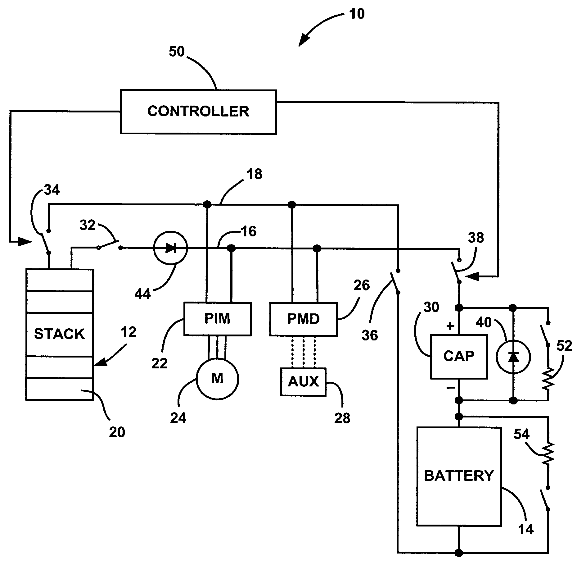
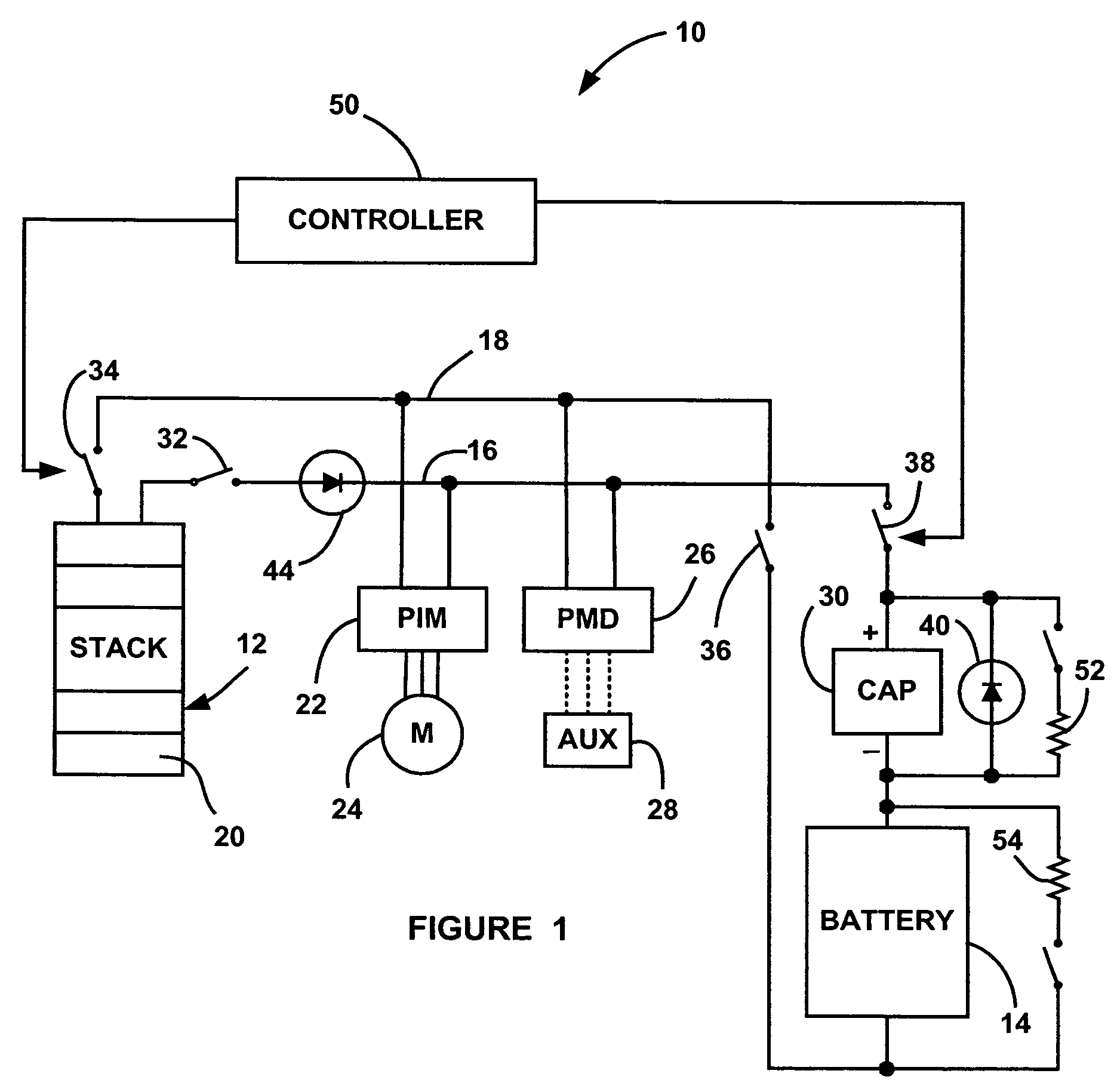
[0016]FIG. 1 is a schematic block diagram of a fuel cell system 10 including a fuel cell stack 12 having a stack of fuel cells 20 electrically coupled in series. The fuel cell stack 12 provides electrical power to a high voltage bus line, represented here as positive bus line 16 and negative bus line 18. In a vehicle fuel cell system, the fuel cell stack 12 may include about 400 cells 20. In this application, the fuel cell stack 12 provides about 280 volts on the bus lines 16 and 18 during a full load demand, and provides about 400 volts on th...


PUM

PropertyMeasurementUnit
poweraaaaaaaaaa
poweraaaaaaaaaa
poweraaaaaaaaaa

Abstract

A fuel cell system that employs a super capacitor and battery electrically coupled in series with each other and in parallel with a fuel cell stack on a power bus line. As the voltage on the power bus line changes over the operating requirements of the system, the super capacitor is charged and discharged over a relatively large voltage swing, such as an 85% SOC swing. The super capacitor equalizes or voltage matches the voltage variation on the power bus line as set by the stack voltage to the voltage of the battery. Therefore, the battery, while providing the majority of the energy and power during charge and discharge, has a relatively small defined SOC swing, which acts to maintain the battery life. The system can also include a diode electrically coupled in parallel with the super capacitor that provides reverse voltage protection and electrical power by-pass.

Description

BACKGROUND OF THE INVENTION[0001]1. Field of the Invention[0002]This invention relates generally to a fuel cell system and, more particularly, to a fuel cell system that employs a battery / capacitor electrical energy storage system that eliminates the need for a DC / DC converter.[0003]2. Discussion of the Related Art[0004]Hydrogen is a very attractive fuel because it is clean and can be used to efficiently produce electricity in a fuel cell. The automotive industry expends significant resources in the development of hydrogen fuel cells as a source of power for vehicles. Such vehicles would be more efficient and generate fewer emissions than today's vehicles employing internal combustion engines.[0005]A hydrogen fuel cell is an electrochemical device that includes an anode and a cathode with an electrolyte therebetween. The anode receives hydrogen gas and the cathode receives oxygen or air. The hydrogen gas is dissociated in the anode to generate free hydrogen protons and electrons. Th...

Claims


Application Information

Patent Timeline
Patent Type & Authority Patents(United States)
IPC IPC(8): H01M8/04
CPCB60L11/1887B60L11/1894H01M16/003H02J7/345B60L11/005B60L11/1803B60L2210/20H02J2001/004Y02T10/7022Y02T10/7016Y02T10/725Y02T90/34Y02T10/7011B60L50/40B60L50/51B60L58/34B60L58/40H02J2300/30Y02E60/50Y02T10/70Y02T10/72Y02T90/40
Inventor RAISER, STEPHEN
Owner GM GLOBAL TECH OPERATIONS LLC
Learn More