Broadband aperture coupled GNSS microstrip patch antenna

a patch antenna and wideband aperture technology, applied in the direction of antenna details, electrically short antennas, antennas, etc., can solve the problems of narrow bandwidth, inability to use high-aperture applications, less desirable multi-path performance, etc., to improve multi-path mitigation, compact structure, and low cost.

Active Publication Date: 2008-09-30
HEMISPHERE GNSS
View PDF14 Cites 22 Cited by
  • Summary
  • Abstract
  • Description
  • Claims
  • Application Information

AI Technical Summary

Benefits of technology

[0011]One advantage of an embodiment disclosed herein is a broadband GPS antenna that covers both the GPS signal band and L-Band signals such as those broadcast by OmniSTAR® for the purpose of differentially correcting a GPS receiver. Another advantage of one or more of the embodiments disclosed herein is a planar antenna with improved multipath mitigation. A further advantage of an embodiment of the invention disclosed here is the combination of radiator, coupling apertures, feed circuit and active circuit into one single printed circuit board (PCB) for compact structure, ease of assembly and low cost. Yet another advantage on one or more exemplary embodiments is that it employs an active circuit that includes a low noise amplifier and band-pass filter that yields high sensitivity when incorporated into the final antenna system.

Problems solved by technology

The ceramic patch is of compact size and has the benefit of low cost but its bandwidth is narrow and it cannot be used in high accuracy applications.
The cross dipole antenna has a high gain at low elevation angles and consequently exhibits less desirable multipath performance.
It also has complicated assembly issues.
This three dimensional microstrip patch antenna has high gain at low elevation angles but it exhibits less desirable multipath performance.
The pinwheel antenna has nice performance including the ability to reduce multipath but it is difficult to manufacture compared to other antenna configurations.
This antenna also exhibits good multipath reducing properties and accuracy but its feed circuit is comparatively complicated, consisting of four coaxial probes and three combiners.

Method used


Image

  • Broadband aperture coupled GNSS microstrip patch antenna
  • Broadband aperture coupled GNSS microstrip patch antenna
  • Broadband aperture coupled GNSS microstrip patch antenna

Examples


Embodiment Construction

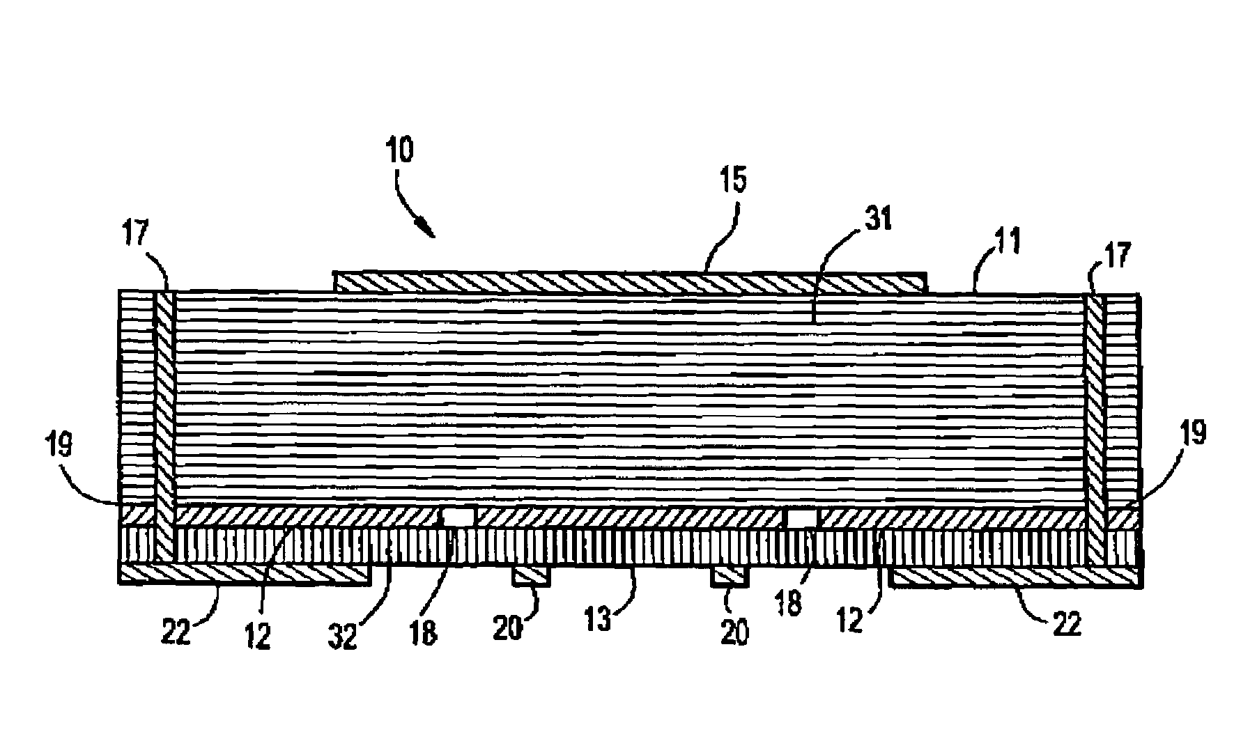
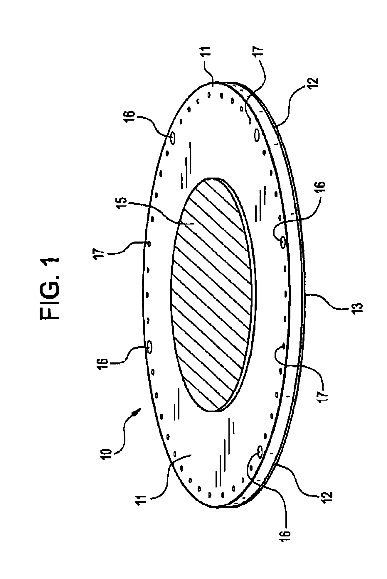
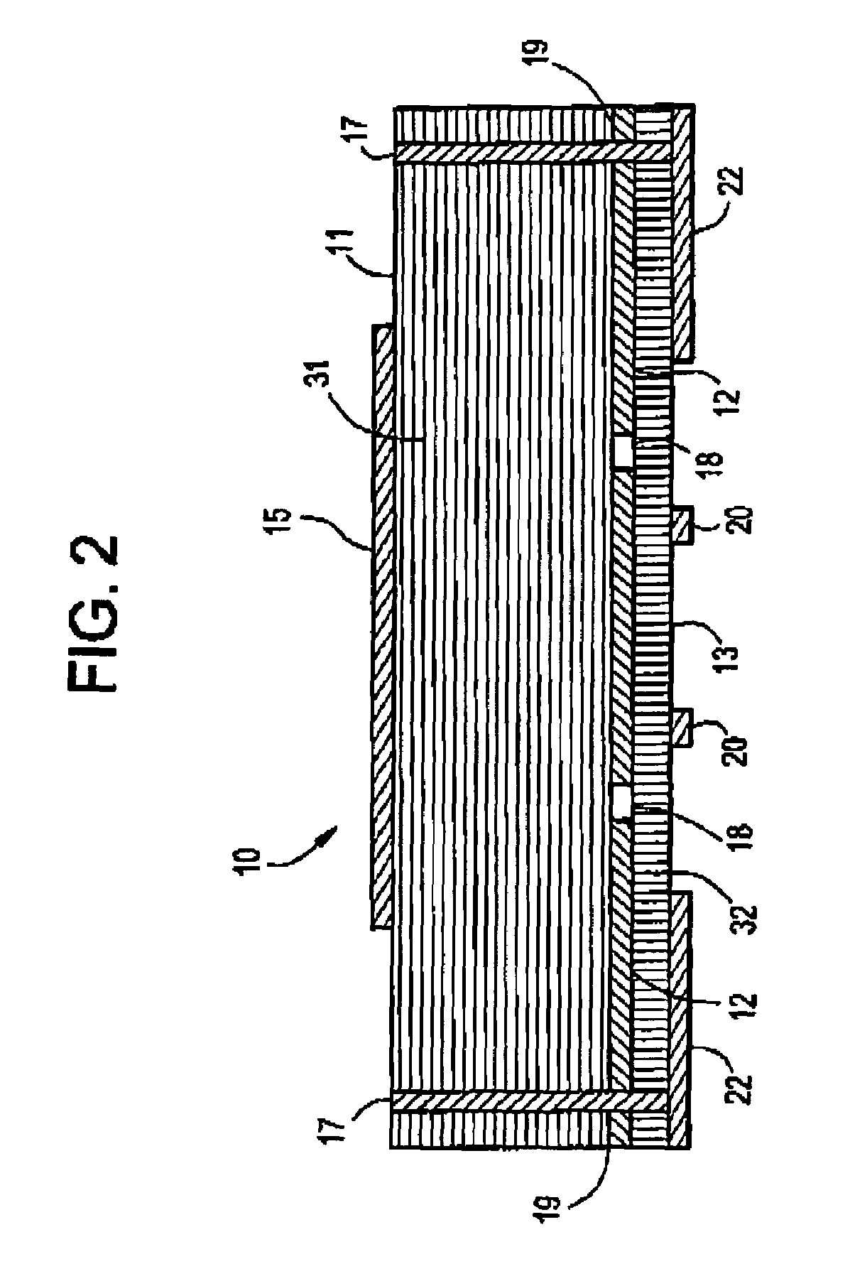
[0020]Disclosed herein in one or more exemplary embodiments is a planar antenna including a circular microstrip patch radiation element etched on the substrate, dual orthogonal apertures on an interior ground plane, and two feed lines, a hybrid coupler and an active circuit on a bottom substrate. When a GNSS signal, and in particular a GPS signal and / or an augmentation signal is picked up by the top layer circular microstrip patch radiation element and coupled to feed lines on the bottom layer by slot apertures on the ground plane, a 90° phase shift is generated by the hybrid coupler and feed lines. The resulting right-hand circularly polarized GPS signal is then directed to a low noise amplifier and filter circuit via one hybrid coupler output port. A load impedance is employed on another output port of the hybrid coupler to absorb the reflecting power from possibly unmatched antenna feed ports. In one exemplary embodiment, the antenna configuration is simulated to enhance and opti...


PUM


Abstract

A multilayer antenna structure configured to receive Global Navigation Satellite System (GNSS) and augmentation signals. The antenna includes a microstrip patch radiation element disposed at a top layer and a ground plane forming a first interior layer, the ground plane including at least two coupling apertures, and the ground plane isolated from said radiation element by a low loss dielectric. The antenna structure also includes a bottom layer, the bottom layer is isolated from the ground plane by another dielectric; at least two feed lines operably connected to a hybrid coupler disposed on the bottom layer; and an active circuit on the bottom layer, a first port of said active circuit operably connected to the hybrid coupler.

Description

FIELD OF THE INVENTION[0001]The invention relates generally to a broadband microstrip antenna as may be employed for radio navigation, more specifically, to an antenna for receiving a right-hand circularly polarized Global Navigation Satellite System (GNSS) signal, particularly a Global Positioning System (GPS) signal.BACKGROUND OF THE INVENTION[0002]A Global Navigation Satellite System (GNSS) includes a network of satellites that broadcast radio signals, enabling a user to determine the location of a receiving antenna with a high degree of accuracy. Examples of GNSS systems include Navstar Global Positioning System (GPS), established by the United States; Globalnaya Navigatsionnay Sputnikovaya Sistema, or Global Orbiting Navigation Satellite System (GLONASS), established by the Russian Federation and similar in concept to GPS; and Galileo, also similar to GPS but created by the European Community and slated for full operational capacity in 2008.[0003]Currently the best-known of the...

Claims


Application Information

Patent Timeline
Patent Type & Authority Patents(United States)
IPC IPC(8): H01Q1/38
CPCH01Q9/0435
Inventor SUN, JIA
Owner HEMISPHERE GNSS
Why Eureka
Try Eureka