
Enhanced light fixture

a technology of enhanced light and diffusers, applied in the field of light fixtures, can solve the problems of ineffective inefficient light distribution in light fixtures, and light exiting the fixture using symmetrically scattering diffusers not typically producing uniform light illumination, etc., to achieve efficient control of light spread, enhance light fixtures, and provide spatial luminance uniformity

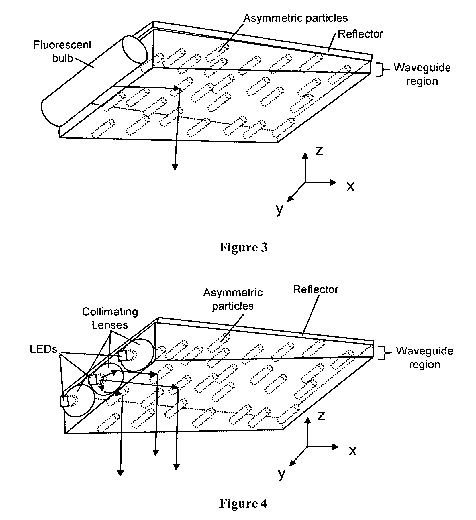
Active Publication Date: 2008-10-07
MASSACHUSETTS DEV FINANCE AGENCY
View PDF11 Cites 91 Cited by
  • Summary
  • Abstract
  • Description
  • Claims
  • Application Information

AI Technical Summary

Benefits of technology

"The present invention is about improving light fixtures by using a special diffuser that controls the spread of light and provides uniform lighting. This diffuser is made up of asymmetrically shaped particles that scatter light in a way that reduces power requirements and cost. The diffuser can be combined with a waveguide to efficiently extract light and create an enhanced light fixture. The technical effects of this invention are improved lighting control, reduced power requirements, cost savings, and improved lighting uniformity."

Problems solved by technology

With the non-symmetric shape of the light fixtures (longer in one direction), the light exiting the fixture using symmetrically scattering diffusers does not typically produce a uniform light illumination.
More than one diffusive element in the path within the light fixture can reduce this effect, but this technique has not been applied to light fixtures.
In other applications when more than one diffuser is used to decrease speckle contrast, symmetric diffusers are typically used and these would inefficiently spread the light in a light fixture.
As a result, more light is absorbed within the fixture due to backscatter and the forward scattered light can scatter inefficiently in undesirable directions.
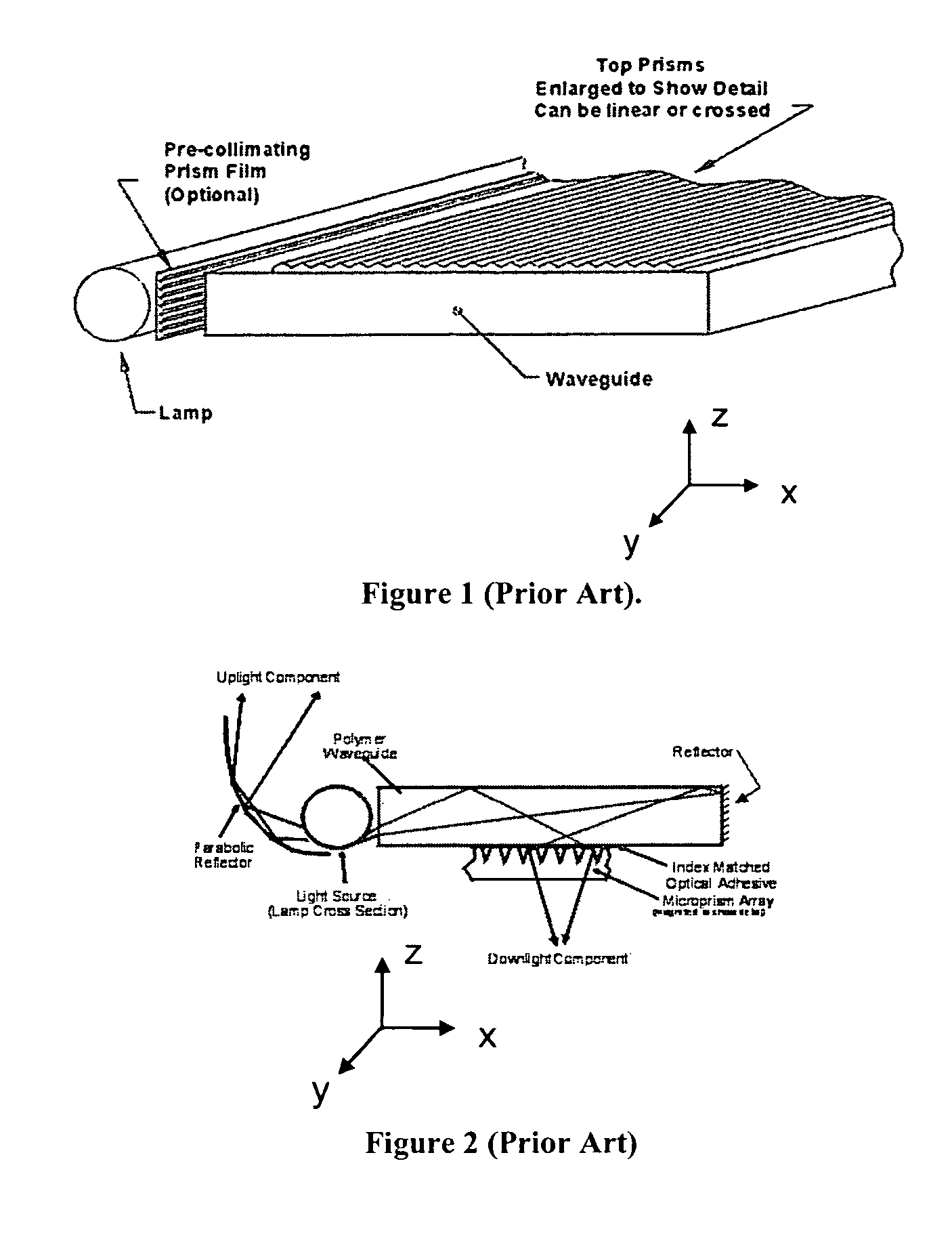
Brushed aluminum surfaces are relatively expensive to manufacture compared to the other diffusing options and are not often used.
Surface relief diffusers can scatter light asymmetrically, however, all surface relief diffusers have a significant amount of backscatter that can reduce optical efficiency.
Additionally, asymmetric surface relief diffusers are typically costly to produce (sometimes requiring expensive holographic mastering and precision casting production techniques) and difficult to clean due to dirt or particles becoming trapped in the inherent holes or pits in the relief structure.
Symmetrically scattering volumetric materials are typically easy to clean but do not efficiently control the scattering of light.
The appearance of these structures can create small bright spots in the fixture that are aesthetically unpleasing.
Often, the materials used are brittle, creating fragile elements that can break easily.
This can increase the fixture volume and the cost of the fixture.
Also, the refractive elements are not easily cleaned due to their surface structure.
Very high isotropic diffusion in the volume or surface will generate a significant amount of backscatter.
As a result, often the uniformity is reduced at the expense of keeping the illuminance high.

Method used


Image

  • Enhanced light fixture
  • Enhanced light fixture
  • Enhanced light fixture

Examples


example 1

[0085]An enhanced light fixture in accordance with the present invention can be produced as described in FIG. 5, that is designed to have increased optical efficiency, increased spatial luminance, be easy to clean, and low cost. This is possible because the volumetric anisotropic scattering film optically coupled to the waveguide more efficiently controls the light scattering. An anisotropic light scattering film is created with scattering particles in a host matrix material by extruding, casting or coating, the mixture containing particles. The particle chosen may be a polystyrene bead of diameter 5 μm dispersed at 10% concentration in a host matrix of acrylic. Other choices of particles and host matrix may provide equivalent performance and details of other methods for creating an anisotropic light scattering film suitable for use in a light fixture are illustrated in U.S. Pat. No. 5,932,342, the text of which is incorporated herein by reference. Asymmetry and alignment of the asy...

example 2

[0086]An enhanced light fixture in accordance with the present invention can be produced as described in FIG. 9, that is designed to have increased optical efficiency, reduced speckle contrast, be easy to clean, and low cost. This is possible because the multiple regions of asymmetrically scattering particles optically coupled to the waveguide more efficiently control the light scattering while reducing speckle contrast. A light diffusing film containing light scattering particles in a host matrix material is created by extruding, casting or coating, the mixture containing particles. The particle chosen may be a polystyrene bead of diameter 5 μm dispersed at 10% concentration in a host matrix of acrylic. Other choices of particles and host matrix can provide equivalent performance. Asymmetry and alignment of the asymmetry can be created by stretching or extrusion processes. A portion of the resulting film containing asymmetric particles is optically coupled to a transparent acrylic ...

example 3

[0087]An enhanced light fixture in accordance with the present invention can be produced as described in FIG. 1, that is designed to have increased optical efficiency, reduced speckle contrast, be easy to clean, and low cost. This is possible because the multiple anisotropic light scattering regions optically coupled to a substrate, creating a waveguide with efficient light scattering, increased spatial luminance uniformity and reducing speckle contrast. A multi-region light diffusing film containing light scattering particles in a host matrix material is created by extruding, casting or coating, the mixture containing particles. A substantially non-scattering material is optically coupled in-between the light scattering regions. The particles chosen may be a polystyrene bead of diameter 5 μm dispersed at 10% concentration in a host matrix of acrylic. Other choices of particles and host matrix can provide equivalent performance. Asymmetry and alignment of the asymmetry can be create...


PUM


Abstract

An enhanced light fixture containing a volumetric, anisotropic diffuser to control the spatial luminance uniformity and angular spread of light from the light fixture is disclosed. The anisotropic diffuser provides increased spatial luminance uniformity and efficient control over the illuminance such that power reductions, reduced cost or reduced size may be achieved. The anisotropic diffuser contains one or more regions of asymmetrically shaped light scattering particles. The spread of illumination of light from a light emitting source can be efficiently controlled by using a thin, low cost, volumetric, asymmetric diffuser to direct the light in the desired direction. This allows the reduction in number of light sources, a reduction in power requirements, or a more tailored illumination. When the anisotropic diffuser is used in combination with a waveguide to extract light, the light is efficiently coupled out of the waveguide in a thin, planar surface. This transmissive diffuser can be coupled to a reflecting element such that the resulting combination is a light reflecting element with a desired asymmetric light scattering profile.

Description

RELATED APPLICATIONS[0001]This application claims the benefit of priority under 35 U.S.C. 119(e) to copending U.S. Provisional Application No. 60 / 628,852, filed on Nov. 17, 2004, the entire contents of which is incorporated herein by reference.FIELD OF THE INVENTION[0002]The invention generally relates to light fixtures, luminaries, lamps or other light emitting devices capable of being used for illumination.BACKGROUND OF THE INVENTION[0003]Fluorescent light bulb based light fixtures are generally rectangular in shape due to the typical long cylindrical shape of the fluorescent bulbs. With the non-symmetric shape of the light fixtures (longer in one direction), the light exiting the fixture using symmetrically scattering diffusers does not typically produce a uniform light illumination.[0004]Improvements in solid state light sources such as light emitting diodes (LEDs) are continuously increasing their efficacy with the luminous output per electrical watt approaching fluorescent sou...

Claims


Application Information

Patent Timeline
Patent Type & Authority Patents(United States)
IPC IPC(8): F21V7/04
CPCG02B5/0242G02B5/0257G02B5/0284G02B6/0041G02B6/0051G02B27/0988F21V1/00F21V2200/20F21Y2105/00G02B6/0055F21S6/00F21S8/08F21V3/049F21W2131/103F21V2200/10F21Y2101/02F21Y2115/10
Inventor YEO, TERENCE E.COLEMAN, ZANE A.
Owner MASSACHUSETTS DEV FINANCE AGENCY
Learn More