High capacity particulate loader and transfer apparatus

a technology of particulate loader and transfer apparatus, which is applied in the direction of conveyors, transportation items, applications, etc., can solve the problems of limiting reducing the life of blowers or rotors, and not providing an acceptable high operating capacity, so as to achieve high capacity and high efficiency. , the effect of high capacity

Inactive Publication Date: 2008-10-07
AG GROWTH IND PARTNERSHIP
View PDF24 Cites 21 Cited by
  • Summary
  • Abstract
  • Description
  • Claims
  • Application Information

AI Technical Summary

Benefits of technology

[0016]The advantage of the present invention is that it provides an improved high capacity particulate loader and transfer apparatus for use by farmers and others for loading grain and other particulate materials from, for example, bins and other storage structures into trucks, trailers, wagons, or other receptacles which provides a dramatic improvement over prior art machines in terms of operating efficiency and capacity. Another advantage is to provide an improved high capacity particulate loader and transfer apparatus having a high efficiency auger airlock assembly and end dump housing which can maintain negative pressure within the auger assembly and loader.
[0017]A still further advantage of the present invention is that it provides an improved high capacity particulate loader and transfer apparatus utilizing a multi-stage suction mechanism for forming a greater source of negative pressure with which to create a high suction, high volume and high speed air stream that draws particulate materials into the loader and thus achieve a higher operating capacity.
[0018]Yet another advantage of the present invention is to provide an improved high capacity particulate loader and transfer apparatus utilizing a multi-stage suction mechanism as noted above, in communication with a separation chamber and a settling chamber, the settling chamber providing an area where dust, fine chaff or other particles from the suctioned particulate or granular materials, which may be present in the air stream, can settle, through gravity, on a surface of the settling chamber, thus reducing contact between particulates and the blowers so as to reduce clogging of the blowers and rotor wear thereof.
[0019]A still further advantage of the present invention is to provide an improved high capacity particulate loader and transfer apparatus which utilizes a variable speed auger, and which comprises a power transfer case for transferring power from a main drive shaft to an intermediate shaft which extends on an angle which corresponds with or substantially corresponds with the angle of the longitudinal axis of the auger to the horizontal. In this manner, regardless of the angle or positioning of the auger in relation to the loader, power to the auger, through use of a corresponding pulley or multi-pulley set linking the intermediate shaft to the lower end of the auger, can be simply and easily provided.

Problems solved by technology

The prior art, although quite satisfactory from a functional standpoint, have limitations in their application when compared to the present invention, and do not provide an acceptably high operating capacity given the fact that these solely use a single stage blower for generating suction or negative pressure for operating such a machine.
Further such machines allow for particulate materials, when the vacuum-generated pickup air stream is drawn through the loader, to come into contact with the rotors of the blower, which permits possible clogging of the blower and / or rotor wear thereof, which, through repeated prolonged contact, can limit or reduce the life span of such blowers or rotors.
However, two related problems have arisen in conventional loader auger air locks or housings.
The first is that materials exiting from the outlet through the airlock doors generally allow, once the airlock door is opened for the discharge of materials, outside air to enter into the barrel or tube, which weakens the vacuum and suction effect.
The second further problem stems from the possibility, once outside air has entered into the barrel or tube of the auger assembly, that material being transported by the auger to be discharged can be blown back down the auger assembly, resulting in what is commonly known as “blowback”.
When this occurs, it is not uncommon for almost all of the vacuum effect to be lost or substantially reduced.

Method used


Image

  • High capacity particulate loader and transfer apparatus
  • High capacity particulate loader and transfer apparatus
  • High capacity particulate loader and transfer apparatus

Examples


Embodiment Construction

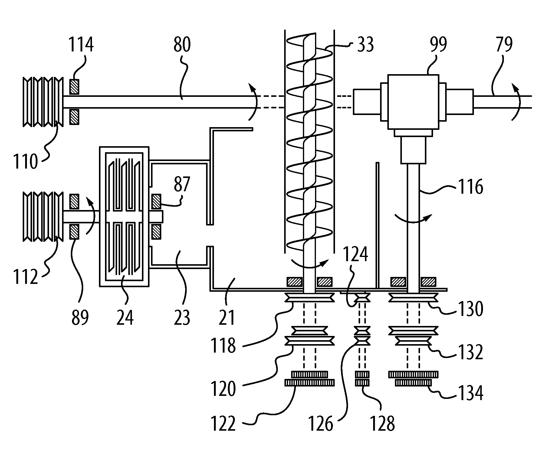
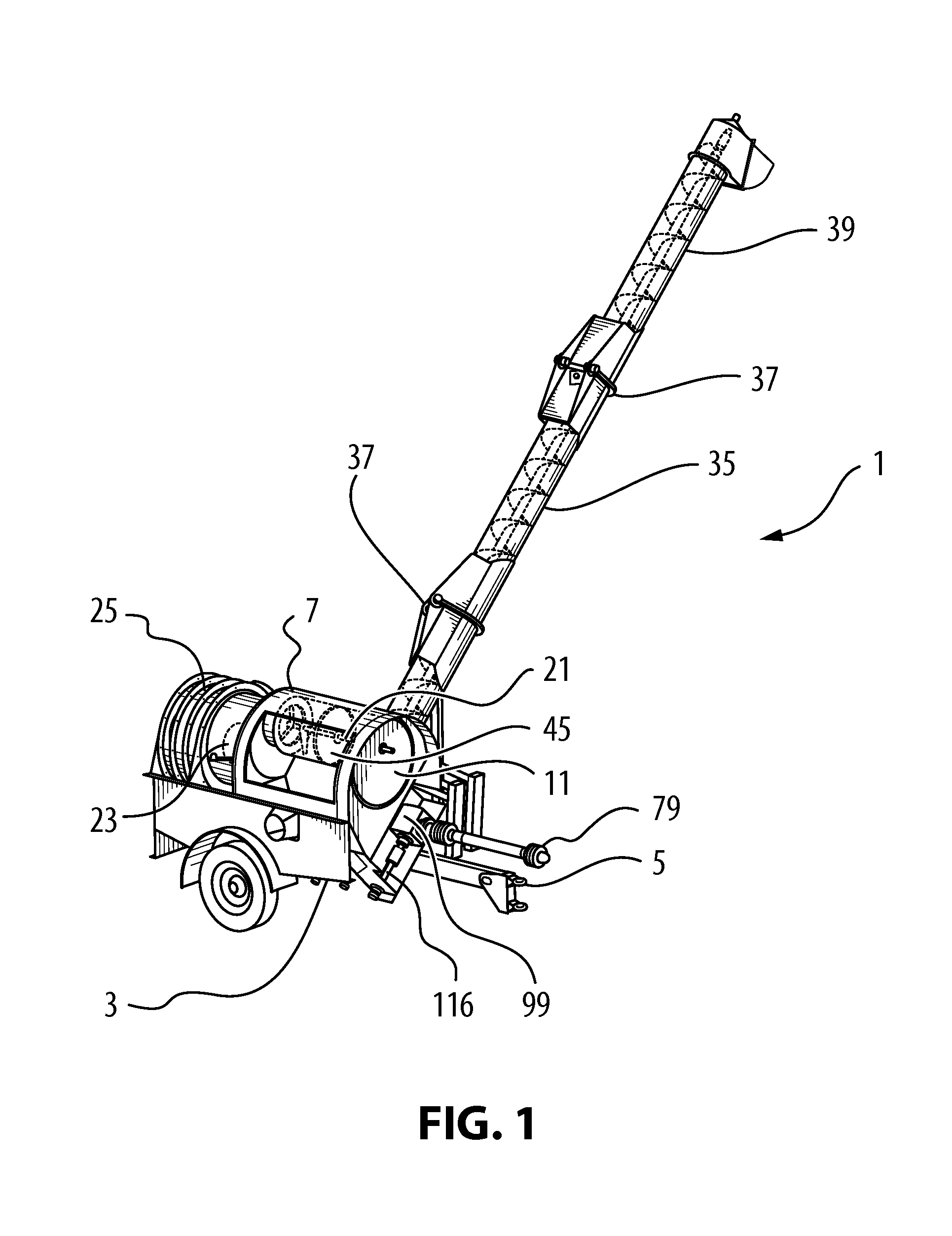
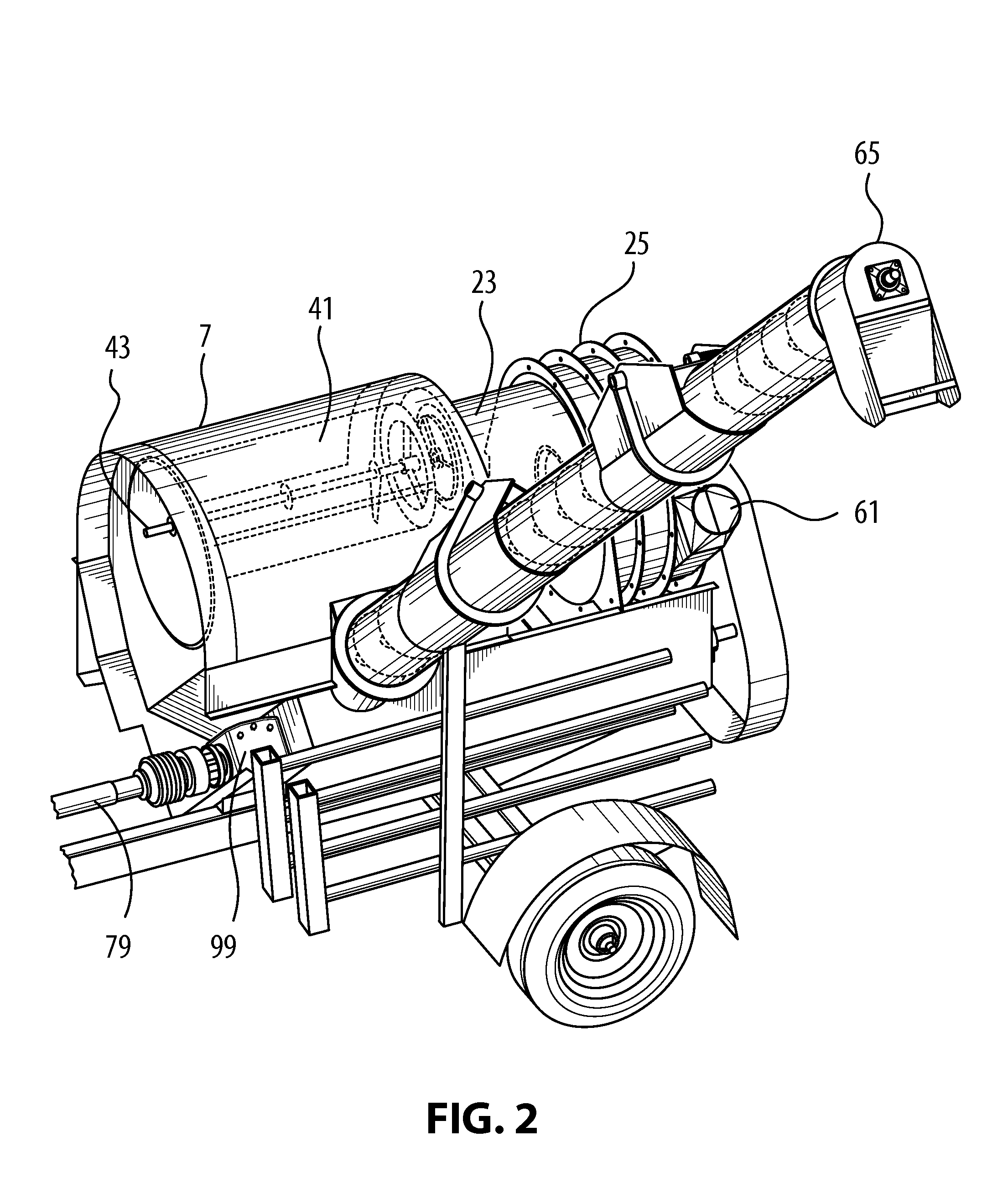
[0036]FIGS. 1 to 13 relate to a high capacity bulk loader 1 for grain, particulate or granular materials which incorporates the principles of the present invention, it being understood that grain, particulate or granular materials (hereinafter referred to as “particulates”) can encompass, for example, grain or agricultural products, fertilizer, chemicals, or other small particulate matter such as styrofoam packing chips or material, glass beads, or other materials which would be apparent to a worker skilled in the art. As illustrated, in one embodiment, a loader 1 includes a wheeled chassis 3 having a forwardly extending tongue 5 by which the loader 1 may be coupled with a towing vehicle (not shown). In an alternative embodiment a non-wheeled, stationary chassis is provided, for permanent or long-term positioning and / or installation at a location, powered for example, by a gasoline or diesel engine or electric motor (not shown). For the purposes of clarity, in this description, the ...


PUM


Abstract

A high capacity particulate loader having an intake hose on one sidewall thereof which communicates with a source of negative pressure formed by a multi-stage suction mechanism, to create a high suction, high volume and high speed air stream that draws particulate materials through the hose and propels them into a separation chamber where they separate from the air stream and are directed into a discharge auger assembly on the opposite sidewall of the loader. The multi-stage suction mechanism communicates with a separation chamber and / or a settling chamber, the settling chamber providing an area where dust or fine chaff from the suctioned particulate materials, which may be present in the air stream, can settle, through gravity, on a bottom surface of the settling chamber, thus avoiding contact with the blowers so as to prevent clogging of the blowers and rotor wear thereof.

Description

FIELD OF THE INVENTION[0001]This invention relates to the field of bulk transfer machines for grain, particulates and granular materials (hereinafter referred to as “particulates”) and, more particularly, to an improved, highly efficient portable unit useable by farmers and others to move and handle particulates.DESCRIPTION OF THE PRIOR ART[0002]Grain and fertilizer collector machines have been commercialized for many years, and represent the underlying technology over which the present invention is a significant improvement. Previous prior art machines have been subject to certain shortcomings which have been overcome in the present invention.[0003]For example, some prior art machines utilize a single stage fan or blower to create suction for the vacuum pickup of the granular or particulate materials, in a negative pressure system. The prior art, although quite satisfactory from a functional standpoint, have limitations in their application when compared to the present invention, a...

Claims


Application Information

Patent Timeline
Patent Type & Authority Patents(United States)
IPC IPC(8): B65G53/08
CPCA01D87/00A01D87/10B65G53/48
Inventor FRANCIS, LANESONNTAG, BOBREMPEL, FRANKNOBLE, MAXDUCLOS, JODY
Owner AG GROWTH IND PARTNERSHIP
Why Eureka
Try Eureka