Nanofilm and membrane compositions

a technology of nanofilms and membranes, applied in the field of nanofilms and membrane compositions, can solve the problems of unmatched building block capabilities of conventional materials, undefined porosity, and inability to define or control porosity by conventional methods, and achieve the effects of high permeability, low permeability, and high permeability

Inactive Publication Date: 2008-10-07
COVALENT PARTNERS LLC
View PDF145 Cites 8 Cited by
  • Summary
  • Abstract
  • Description
  • Claims
  • Application Information

AI Technical Summary

Benefits of technology

[0009]In some variations, the thickness of a nanofilm is less than about 30 nanometers, sometimes less than about 4 nanometers, and sometimes less than about 1 nanometer.
[0010]A nanofilm may have a filtration function that may be used to describe the species that pass through the nanofilm. A nanofilm may be permeable only to a particular species in a particular fluid and specie

Problems solved by technology

These building block capabilities are unparalleled conventional materials and methods such as polymerizations which produce statistical mixtures or confinement of reactants to enhance certain reaction pa

Method used


Image

  • Nanofilm and membrane compositions
  • Nanofilm and membrane compositions
  • Nanofilm and membrane compositions

Examples


example 1

Derivatization of Silicon Substrates with (3-aminopropyl)triethoxysilane (APTES)

[0268]SiO2 substrates were first sonicated in a piranha solution (3:1 ratio of H2SO4:30% H2O2) for 15 minutes. This was followed by a 15 min sonication in Milli-Q water (>18 MΩ-cm). The derivatization step was done in a glove bag under a N2 atmosphere. 0.05 mL APTES and 0.05 mL pyridine were added to 9 mL of toluene. Immediately following mixing, the freshly cleaned SiO2 substrates were immersed in the APTES solution for 10 min. Substrates were washed with copious amounts of toluene and then dried with N2. Deposited APTES films showed a range of thickness values from 0.8 to 1.3 nm.

example 2

[0269]Amphiphilic modules Hexamer 1a were dissolved in HPLC-grade chloroform at a concentration of approximately 1 mg / ml. The chloroform solution was applied to a water (Millipore Milli-Q) surface in an L-B trough (KSV, Helsinki). The chloroform was allowed to evaporate, leaving the amphiphilic modules on the surface of the water with their hydrophilic groups immersed in the water and their lipophilic groups in the air. The temperature in the system was controlled (approximately ±0.2° C.). The barriers of the L-B trough were slowly compressed (1-10 mm / min). The surface pressure was monitored using the Wilhelmy procedure during film compression. The shape of the isotherm confirmed that the module formed a Langmuir film on the surface of the water.

example 3

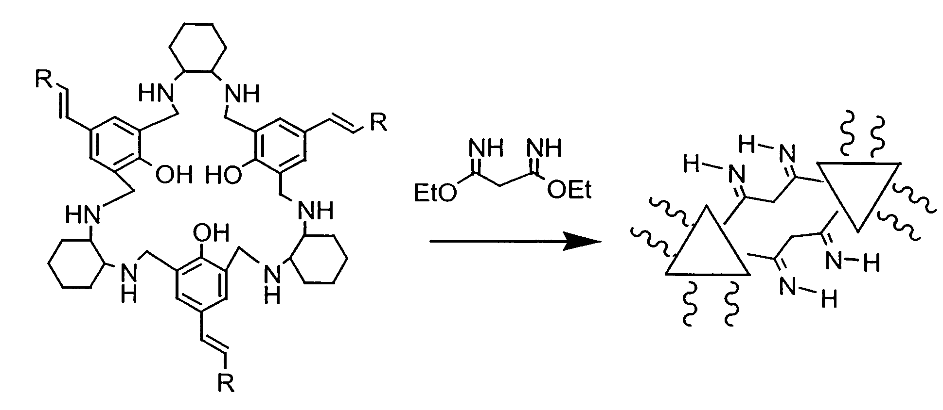
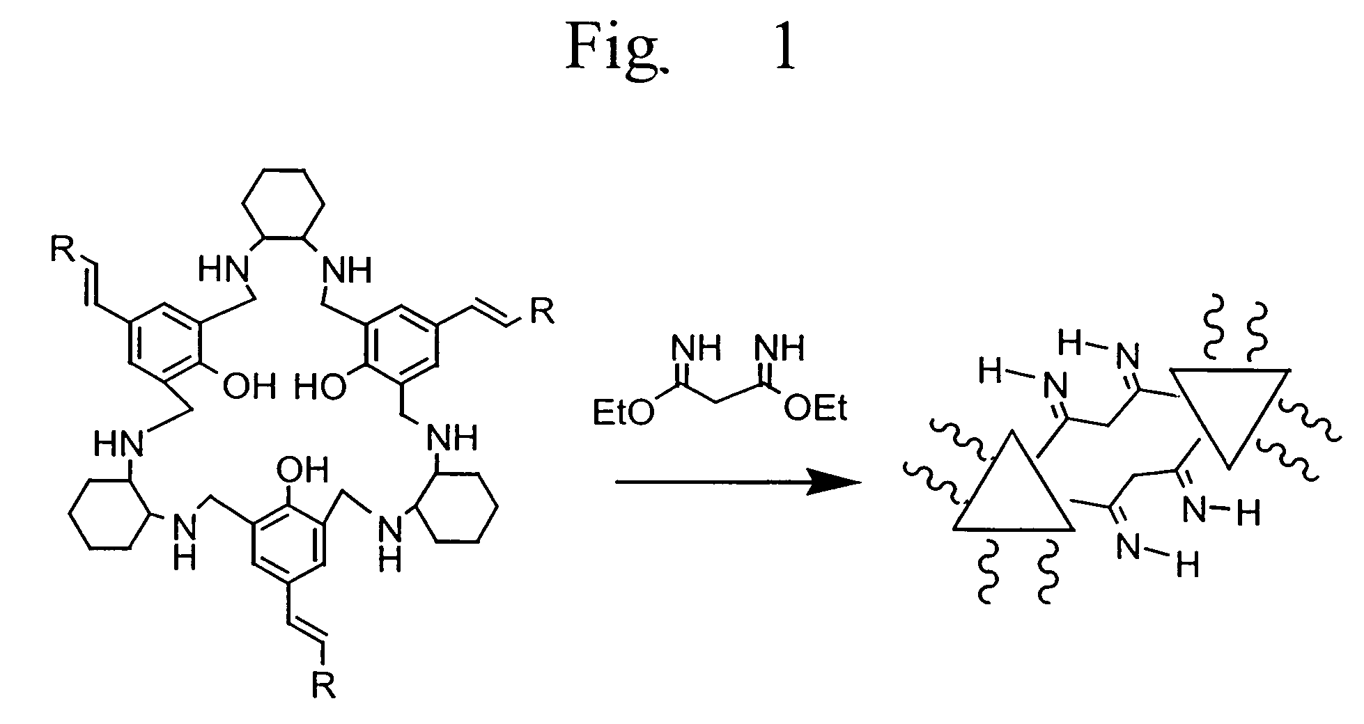
Hexamer 1dh with DEM (Langmuir-Blodgett Deposition)

[0270]The scheme for this preparation is illustrated in FIG. 1. 25 μl of a 1 mg / ml solution of Hexamer 1dh in chloroform were spread on a 2 mg / ml diethyl malonimidate (DEM) in water subphase (pH 8.8, T=22° C.). After waiting for 19 minutes to allow for spreading solvent evaporation, the monolayer was compressed and held at 5 mN / m. The subphase was then heated to 40° C. and held for approximately 60 minutes. A rigidified solid nanofilm was formed on the surface of the subphase, which appeared uniform and homogeneous in a Brewster Angle microscope image. When touched with a probe, the film was cracked, as shown by the Brewster Angle microscope image obtained for the film directly on the surface of the subphase, illustrated in FIG. 6A. This indicates that the nanofilm was highly cross-linked. Mass spectral analysis of the rigid nanofilm could not be performed because the solid nanofilm clogged the input of the instrument.

[0271]Another ...


PUM

PropertyMeasurementUnit
Timeaaaaaaaaaa
Thicknessaaaaaaaaaa
Thicknessaaaaaaaaaa

Abstract

Nanofilms useful for filtration are prepared from oriented amphiphilic molecules and oriented macrocyclic modules. The amphiphilic species may be oriented on an interface or surface. The nanofilm may be prepared by depositing or attaching an oriented layer to a substrate. A nanofilm may also be prepared by coupling the oriented macrocyclic modules to provide a membrane.

Description

CROSS REFERENCE TO RELATED APPLICATIONS[0001]This application claims priority to U.S. Provisional Application Ser. No. 60 / 383,236, filed May 22, 2002, and is a continuation-in-part of U.S. application Ser. No. 10 / 226,400, filed Aug. 23, 2002, which is a continuation-in-part of U.S. application Ser. No. 10 / 071,377, filed Feb. 7, 2002, herein incorporated by reference in their entirety.TECHNICAL FIELD[0002]This invention relates variously to thin layer compositions of coupled oriented amphiphilic macrocyclic modules, nanofilms having particular permeation properties, and nanofilms for filtration and separation. The thin layer nanofilms may be applied to a variety of selective permeation processes.BACKGROUND OF THE INVENTION[0003]Nanotechnology involves the ability to engineer novel structures at the atomic and molecular level. One area of nanotechnology is to develop chemical building blocks from which hierarchical molecules of predicted properties can be assembled. An approach to mak...

Claims


Application Information

Patent Timeline
IPC IPC(8): C07D291/00B82B1/00C07D259/00C07D471/22C08J5/18
CPCB82Y30/00C07D259/00
Inventor KRIESEL, JOSHUA W.KARPISHIN, TIMOTHY B.BIVIN, DONALD B.MERRILL, GRANTEDELSTEIN, MARTIN S.SMITH, THOMAS H.WHITEFORD, JEFFERY A.JONAS, ROBERT T.MICKLATCHER, MARKJOSHI, SERENA
Owner COVALENT PARTNERS LLC
Why Eureka
Try Eureka