Data transmission method and equipment

a data transmission and data technology, applied in the field of data transmission methods, can solve problems such as inefficient methods, interference to telecommunications, delay in transmission, etc., and achieve the effects of reducing diversity, facilitating transmission, and facilitating transmission

Inactive Publication Date: 2008-10-07
NOKIA TECHNOLOGLES OY
View PDF13 Cites 17 Cited by
  • Summary
  • Abstract
  • Description
  • Claims
  • Application Information

AI Technical Summary

Benefits of technology

[0020]In a preferred embodiment of the invention, secondary pilot signals are transmitted sequentially, i.e. with power levels that vary in time. This can be achieved e.g. by transmitting several secondary pilot signals to the same radiation pattern by means of using different channelization codes, such that the signals alternately strengthen and weaken one another. The advantage is that even though the average power level is the same, the signal-to-interference ratio is better since channel estimation can be centred on the instants when the pilot is strong. Furthermore, in the preferred embodiments of the invention a dedicated pilot signal is transmitted with at least one user signal at an adjustable transmit power level. The arrangements utilize a new type of asymmetrical channel estimate. In the signals that are transmitted with a strong primary common pilot, the power level of the dedicated pilot can be adjusted to a low level. In the signals transmitted with a weak secondary common pilot, the power level of the dedicated pilot is adjusted to a relatively higher value than in the signals transmitted with the primary pilot. In a preferred embodiment of the invention, an asymmetrical channel estimate is applied by favouring a signal comprising the primary common pilot. During transmission, the transmit antenna path proved to have a channel with a good channel estimate can be favoured by increasing the data transmit power thereof with respect to the other transmission routes.
[0023]The method and the equipment according to the invention provide several advantages. The arrangements according to the preferred embodiments of the invention ensure high pilot signal quality also for terminal equipments that are not capable of utilizing more than two transmit antennas in connection with transmit diversity. On the other hand, the terminal equipments that are able to do this can utilize transmit diversity as planned. During reception of a signal transmitted with a radio pattern including a secondary common pilot signal, channel estimation is possibly carried out based on both the dedicated pilot signal and the secondary common pilot signal. Furthermore, since the number of equipments utilising only a smaller degree of diversity will likely decrease in the future as the users exchange their equipments for the latest models, in preferred embodiments of the invention the weighting of the pilot signals can be changed so as to favour more the terminal equipments that are capable of receiving transmissions transmitted with more than two antennas. The operator of the system will thus be better equipped to make the system operate more effectively.

Problems solved by technology

As well known, the transmission path used for transmitting signals in telecommunication connections causes interference to telecommunications.
Other simultaneous connections may also cause interference, which may change as a function of time and place.
However, a drawback is delays in transmission, especially when the channel is a slowly fading one.
However, this is an inefficient method when the channel has a wide coherence bandwidth.
A drawback of reception diversity is the difficulty of implementing two antennas in a terminal equipment that should be as small as possible.
Particularly transmission of pilot signals is problematic since primary pilot signals can only be transmitted via two transmission routes.
A drawback of this method is that the terminal equipments capable of receiving a signal transmitted with only two antennas lose some of the pilot signal power.
This creates problems for the terminal equipments since the measurements to be carried out on the pilot (for handover and cell selection) will become more difficult as the power of the pilot signal decreases.
Furthermore, this method cannot be applied to more than four transmit antennas without adding new channelization codes.

Method used


Image

  • Data transmission method and equipment
  • Data transmission method and equipment
  • Data transmission method and equipment

Examples


Embodiment Construction

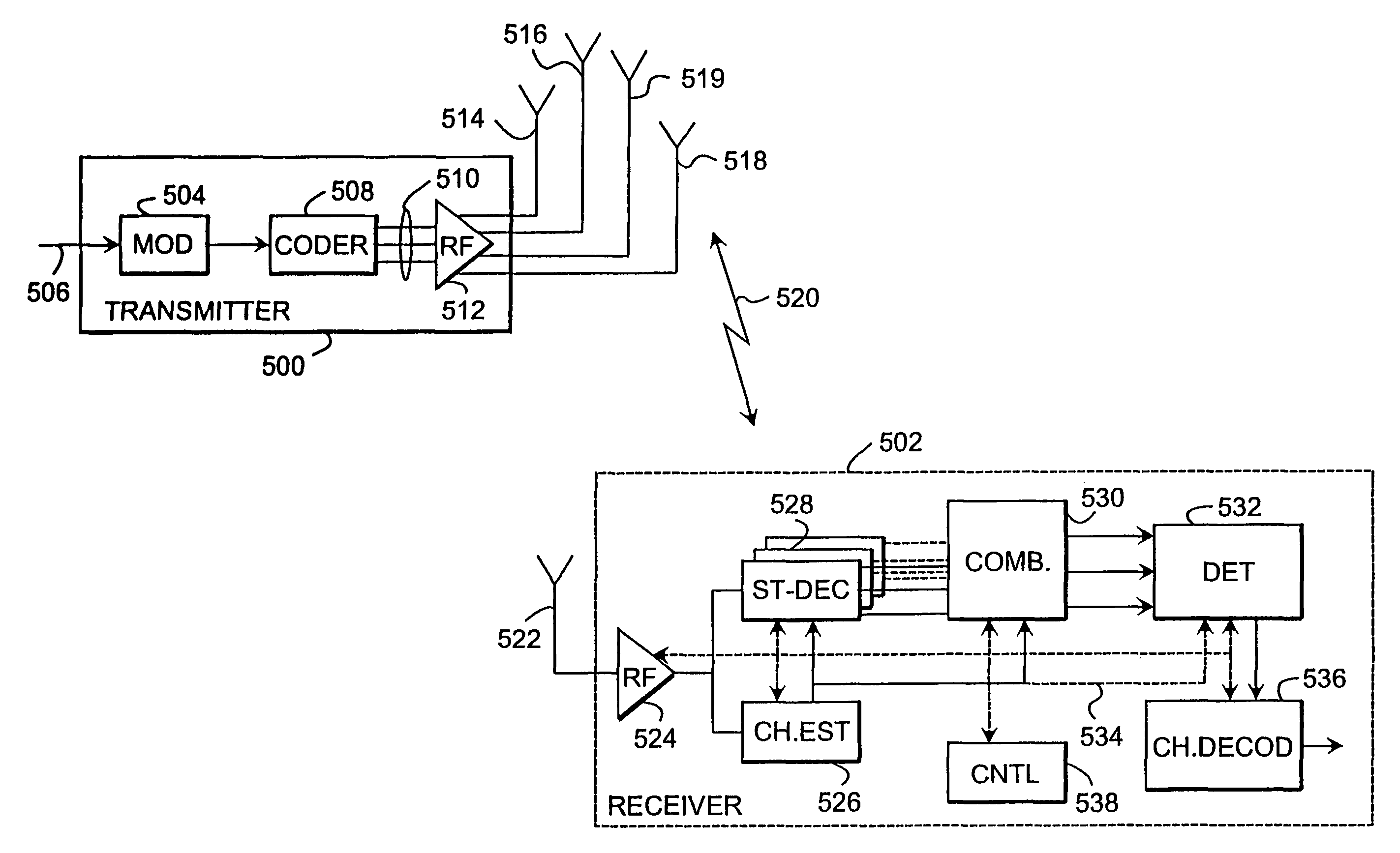
[0034]The invention can be applied in radio systems where at least a part of a signal can be transmitted with three or more transmit antennas or with three or more beams provided by several transmit antennas. A transmission channel can be formed by means of e.g. time division, frequency division or code division symbol multiplexing or multiple access method. Systems utilizing combinations of different multiple access methods are also covered by the scope of the invention. The examples illustrate the use of the invention in a universal mobile telecommunication system (UMTS) employing a wideband code division multiple access method (WCDMA) implemented with a direct sequence technique, without restricting the invention thereto, however.

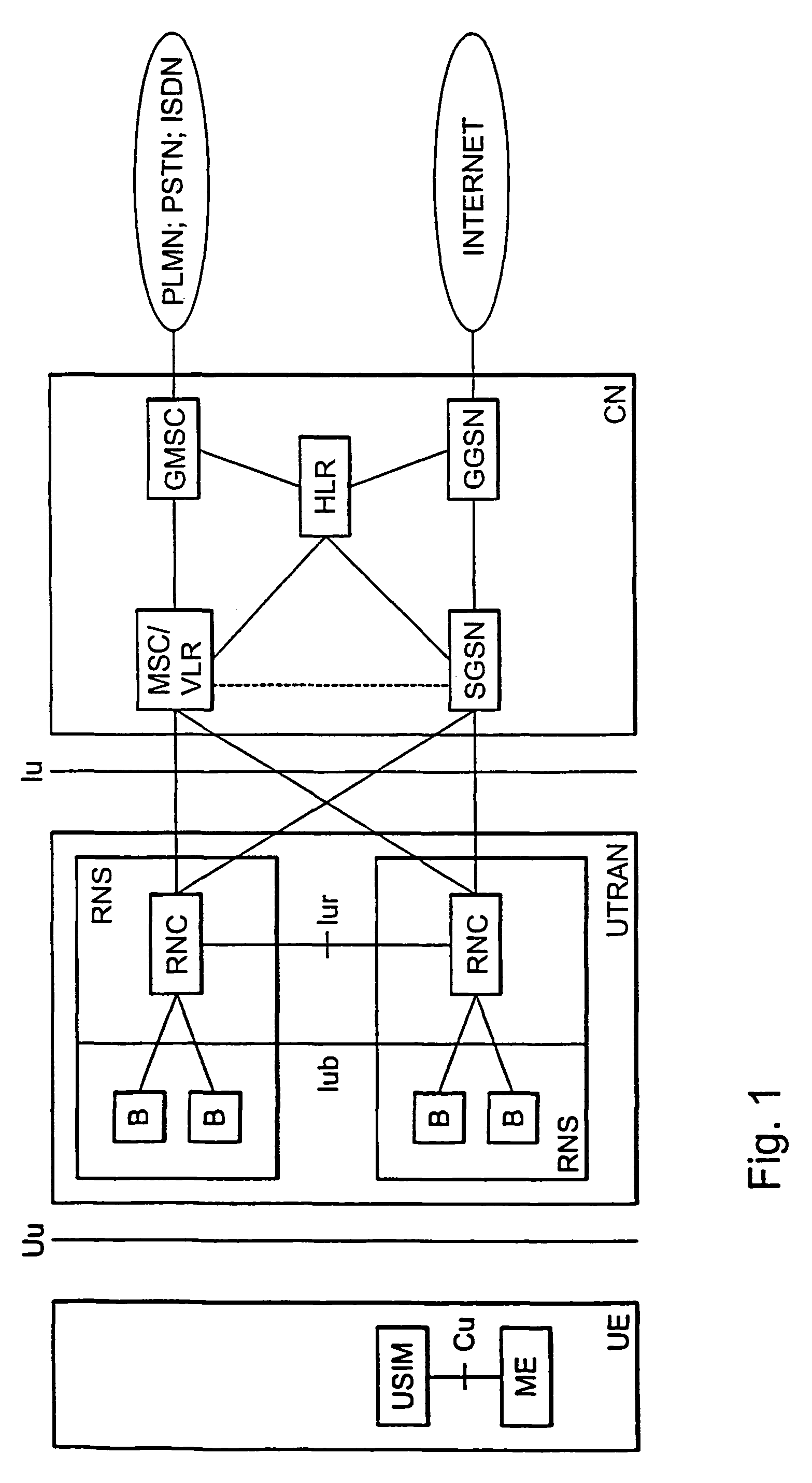
[0035]With reference to FIG. 1, the structure of a mobile telephone system will be described by way of an example. The main components of a mobile telephone system include a core network CN, a UMTS terrestrial radio access network UTRAN and a user equipm...


PUM


Abstract

Equipment for transmitting a signal, the equipment comprising an antenna array (600-606) for providing three or more radiation antenna patterns. The equipment is arranged to transmit a primary common pilot signal with at most two radiation patterns and a secondary common pilot signal with at least one radiation pattern. The equipment comprises controllers (622a-622d) for adjusting the power ratio between the primary and the secondary common pilot signal and the total power of the primary and the secondary common pilot signals, and controllers (614a-614d) for adjusting the transmit power of the dedicated pilot signal, such that the power levels of the dedicated pilot signals transmitted with the same radiation patterns as the secondary common pilot signal are relatively higher than the power levels of the dedicated pilot signals transmitted with the same radiation patterns as the primary common pilots.

Description

FIELD OF THE INVENTION[0001]The invention relates to a data transmission method used particularly in connection with transmit diversity. The invention further relates to equipment that is suitable for transmitting a signal and to equipment suitable for receiving a signal.BACKGROUND OF THE INVENTION[0002]As well known, the transmission path used for transmitting signals in telecommunication connections causes interference to telecommunications. This occurs irrespective of the physical form of the transmission path, i.e. whether the transmission path is a radio connection, an optical fibre or a copper cable, for instance. Particularly in radio communications, situations often occur where the quality of the transmission path varies from one connection to another and also during a connection.[0003]Fading on a radio path is a typical phenomenon causing changes in a transmission channel. Other simultaneous connections may also cause interference, which may change as a function of time and...

Claims


Application Information

Patent Timeline
Patent Type & Authority Patents(United States)
IPC IPC(8): H04B7/216H04B7/005H04B7/06
CPCH04B7/0619H04W52/322H04W52/325H04B7/0617H04B7/0669H04B7/0691H04W52/42
Inventor KAIPAINEN, YRJOTIRKKONEN, OLAVKUUSELA, MARKKU
Owner NOKIA TECHNOLOGLES OY
Why Eureka
Try Eureka