System and method of CT imaging with second tube/detector patching

a technology of ct imaging and second tube, applied in the field of diagnostic imaging, can solve the problems of inability to provide independent data or feedback as to the energy and incident flux rate of photons, ct imaging would not be a viable diagnostic imaging tool, and inability to provide energy discriminatory data or otherwise count the number and/or measure the energy of photons actually received by a given detector element or pixel, etc., to achieve better visualization, reduce the effect of beam hardening, and boost the contrast ratio ratio ratio ratio ratio ratio ratio ratio ratio ratio ratio ratio ratio ratio ratio ratio ratio ratio ratio ratio ratio ratio ratio ratio ratio ratio ratio ratio ratio ratio ratio ratio ratio ratio ratio ratio ratio ratio ratio ratio ratio ratio ratio ratio ratio ratio ratio ratio ratio ratio ratio ratio ratio ratio ratio ratio ratio ratio ratio ratio ratio ratio ratio ratio ratio ratio ratio ratio ratio ratio ratio ratio ratio ratio ratio ratio ratio ratio ratio ratio ratio ratio ratio ratio ratio ratio ratio ratio ratio ratio ratio ratio ratio ratio ratio ratio ratio ratio ratio ratio ratio ratio ratio ratio ratio ratio ratio ratio ratio ratio ratio ratio ratio ratio ratio ratio ratio ratio ratio ratio ratio ratio ratio ratio ratio ratio ratio ratio ratio ratio ratio ratio ratio ratio ratio ratio ratio ratio ratio ratio ratio ratio ratio ratio ratio ratio ratio ratio ratio ratio ratio ratio ratio ratio ratio ratio ratio ratio ratio ratio ratio ratio ratio ratio ratio ratio ratio ratio ratio ratio ratio ratio ratio ratio ratio ratio ratio ratio ratio ratio ratio ratio ratio ratio ratio ratio ratio ratio ratio ratio ratio ratio ratio ratio ratio ratio ratio ratio ratio ratio ratio ratio ratio ratio ratio ratio ratio ratio ratio ratio ratio ratio ratio ratio ratio ratio ratio ratio ratio ratio ratio ratio ratio ratio ratio ratio ratio ratio ratio ratio ratio ratio ratio ratio ratio ratio ratio ratio ratio ratio ratio ratio ratio ratio ratio ratio ratio ratio ratio ratio ratio ratio ratio ratio ratio ratio ratio ratio ratio ratio ratio ratio ratio ratio ratio ratio ratio ratio ratio ratio ratio ratio ratio ratio ratio ratio ratio ratio ratio ratio ratio ratio ratio ratio ratio ratio ratio ratio ratio ratio ratio ratio ratio ratio ratio ratio ratio ratio ratio ratio ratio ratio ratio ratio ratio ratio ratio ratio ratio ratio ratio ratio ratio ratio ratio ratio ratio ratio ratio ratio ratio ratio ratio ratio ratio ratio ratio ratio ratio ratio ratio ratio ratio ratio ratio ratio ratio ratio ratio ratio ratio ratio ratio ratio ratio ratio ratio ratio ratio ratio ratio ratio ratio ratio ratio ratio ratio ratio ratio ratio ratio ratio ratio ratio ratio ratio ratio ratio ratio ratio ratio ratio ratio ratio ratio ratio ratio ratio ratio ratio ratio ratio ratio ratio ratio ratio ratio ratio ratio ratio ratio ratio ratio ratio

Active Publication Date: 2008-10-07
GENERAL ELECTRIC CO
View PDF3 Cites 56 Cited by
  • Summary
  • Abstract
  • Description
  • Claims
  • Application Information

AI Technical Summary

Benefits of technology

[0014]A spectral CT system with second tube / detector data patching is disclosed. The CT detector includes a semi-conductor layer having a plurality of pixelated anodes attached thereto. The CT detector supports not only x-ray photon counting, but energy measurement or tagging and energy integration as well. As a result, the present invention supports the acquisition of both anatomical detail as well as tissue characterization information. In this regard, the energy discriminatory information or data may be used to reduce the effects of beam hardening and the like. Furthermore, these detectors support the acquisition of tissue discriminatory data and therefore provide diagnostic information that is indicative of disease or other pathologies. This detector can also be used to detect, measure, and characterize materials that may be injected into the subject such as contrast agents and other specialized materials by the use of optimal energy weighting to boost the contrast of iodine and calcium (and other high atomic or materials). Contrast agents can, for example, include iodine that is injected into the blood stream for better visualization.

Problems solved by technology

A drawback of such detectors is their inability to provide independent data or feedback as to the energy and incident flux rate of photons detected.
While it is generally recognized that CT imaging would not be a viable diagnostic imaging tool without the advancements achieved with conventional CT detector design, a drawback of these integrating detectors is their inability to provide energy discriminatory data or otherwise count the number and / or measure the energy of photons actually received by a given detector element or pixel.
A drawback of photon counting detectors is that these types of detectors have limited count rates and have difficulty covering the broad dynamic ranges encompassing very high x-ray photon flux rates typically encountered with conventional CT systems.
What can be problematic, however, is that the bowtie filter may not be optimum given that a subject population is significantly less than uniform and not exactly cylindrical in shape nor centrally located in the x-ray beam.
In such cases, it is possible for one or more disjointed regions of saturation to occur or conversely to over-filter the x-ray flux and unnecessarily create regions of very low flux.
Low x-ray flux in the projection results in a reduction in information content which will ultimately contribute to unwanted noise in the reconstructed image of the subject.
However, this solution leads to increased scan time.
That is, there is a penalty in that the acquisition time for the image is increased in proportion to the nominal flux needed to acquire a certain number of x-rays that meet image quality requirements.
However, for configurable mode detectors the full dynamic range may not be available and saturation may yet occur.
However, these systems do not include photon-counting capability, nor do such systems have the capability to re-bin or simultaneously correct the saturated data in one detector sub-system with data from an unsaturated detector sub-system.

Method used


Image

  • System and method of CT imaging with second tube/detector patching
  • System and method of CT imaging with second tube/detector patching
  • System and method of CT imaging with second tube/detector patching

Examples


Embodiment Construction

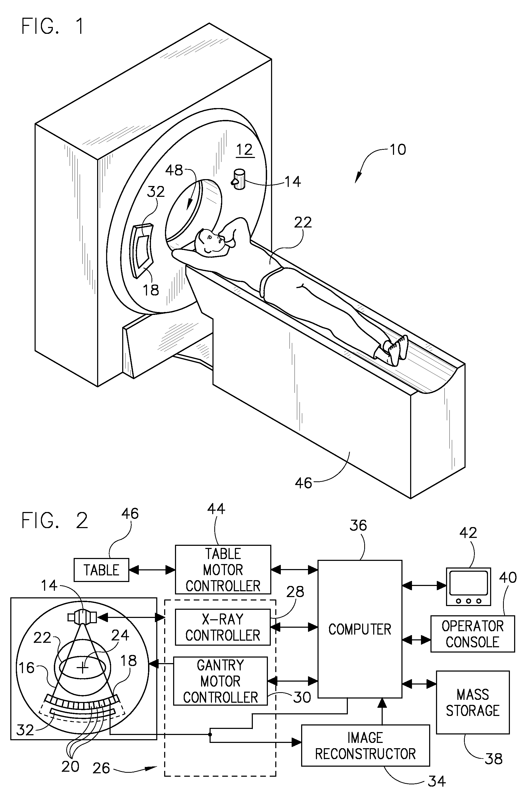
[0029]Diagnostics devices comprise x-ray systems, magnetic resonance (MR) systems, ultrasound systems, computed tomography (CT) systems, positron emission tomography (PET) systems, ultrasound, nuclear medicine, and other types of imaging systems. Applications of x-ray sources comprise imaging, medical, security, and industrial inspection applications. However, it will be appreciated by those skilled in the art that an implementation is applicable for use with single-slice or other multi-slice configurations. Moreover, an implementation is employable for the detection and conversion of x-rays. However, one skilled in the art will further appreciate that an implementation is employable for the detection and conversion of other high frequency electromagnetic energy. An implementation is employable with a “third generation” CT scanner and / or other CT systems.

[0030]The operating environment of the present invention is described with respect to a sixty-four-slice computed tomography (CT) ...


PUM


Abstract

A CT imaging system includes a rotatable gantry having an opening to receive an object to be scanned, a first x-ray emission source attached to the rotatable gantry and configured to emit x-rays toward the object, and a second x-ray emission source attached to the rotatable gantry and configured to emit x-rays toward the object. A first detector is configured to receive x-rays that emit from the first x-ray emission source, and a second detector configured to receive x-rays that emit from the second x-ray emission source. A first portion of the first detector is configured to operate in an integration mode and a first portion of the second detector is configured to operate in at least a photon-counting mode.

Description

BACKGROUND OF THE INVENTION[0001]The present invention relates generally to diagnostic imaging and, more particularly, to a system and method of correcting saturated data occurring in photon-counting and configurable mode detectors.[0002]Typically, in computed tomography (CT) imaging systems, an x-ray source emits a fan-shaped beam toward a subject or object, such as a patient or a piece of luggage. Hereinafter, the terms “subject” and “object” shall include anything capable of being imaged. The beam, after being attenuated by the subject, impinges upon an array of radiation detectors. The intensity of the attenuated beam radiation received at the detector array is typically dependent upon the attenuation of the x-ray beam by the subject. Each detector element of the detector array produces a separate electrical signal indicative of the attenuated beam received by each detector element. The electrical signals are transmitted to a data processing system for analysis which ultimately ...

Claims


Application Information

Patent Timeline
Patent Type & Authority Patents(United States)
IPC IPC(8): H05G1/26
CPCA61B6/032A61B6/4014A61B6/4241G01T1/2985
Inventor TKACZYK, JOHN ERICBASU, SAMIT KUMARWU, XIAOYEDU, YANFENG
Owner GENERAL ELECTRIC CO
Why Eureka
Try Eureka