Reducing shared downlink radio channel interference by transmitting to multiple mobiles using multiple antenna beams

a technology of antenna beams and shared downlink radio channels, applied in diversity/multi-antenna systems, data switching networks, wireless communication, etc., can solve problems such as insufficient robustness of coding and modulation schemes to ensure transmission with a low error rate, and degrade system performan

Active Publication Date: 2008-10-14
TELEFON AB LM ERICSSON (PUBL)
View PDF15 Cites 42 Cited by
  • Summary
  • Abstract
  • Description
  • Claims
  • Application Information

AI Technical Summary

Benefits of technology

[0002]Shared downlink radio channels, like the high speed-downlink shared channel (HS-DSCH) employed in third generation, wideband code division multiple access (WCDMA) systems, offer high data transmission rates, reduced round-trip delays, and high capacity, at least with respect to a typical transport channel. The HS-DSCH supports higher order modulation to achieve higher user and system throughput, fast link adaptation that takes into account the instantaneous quality of the radio propagation environment and adapts the coding and modulation scheme accordingly, and hybrid-ARQ with soft combining to decrease retransmissions and thereby reduce delay.
[0005]This difference between a reported CQI and the actual CQI at the scheduled HS-DSCH transmission is particularly problematic in adaptive antenna systems. An adaptive antenna system can change its beam characteristics in response to changes in the network. An antenna beam is any signal transmission deliberately covering only part of a cell. A cell is a coverage area of the base station. Because the base station can detect the direction of a mobile station, it can transmit dedicated information in an antenna beam towards the desired mobile station. By directing the signal just toward its recipient, the interference in the network can be substantially reduced. Adaptive antennas can significantly increase the data capacity in a cellular radio network.
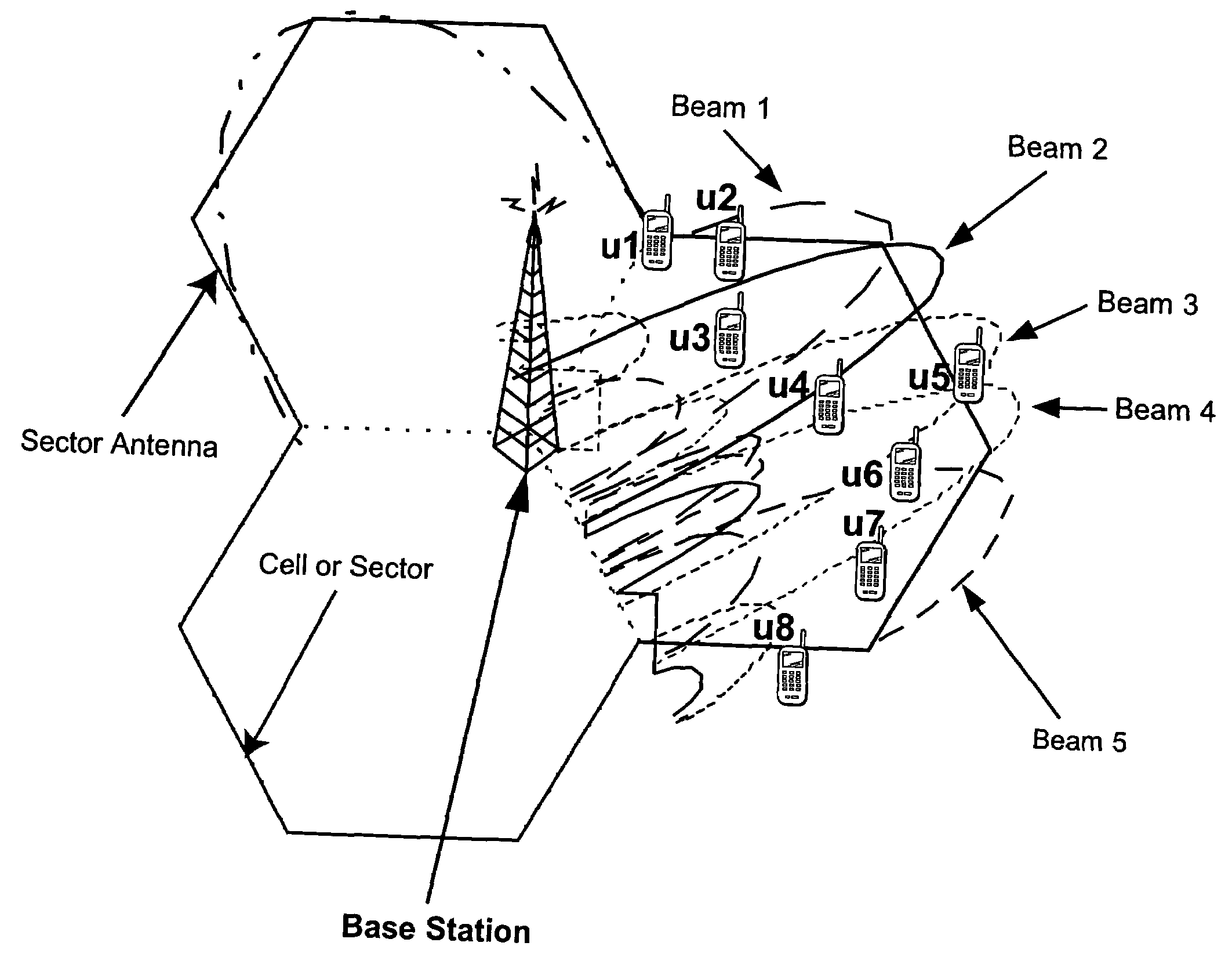
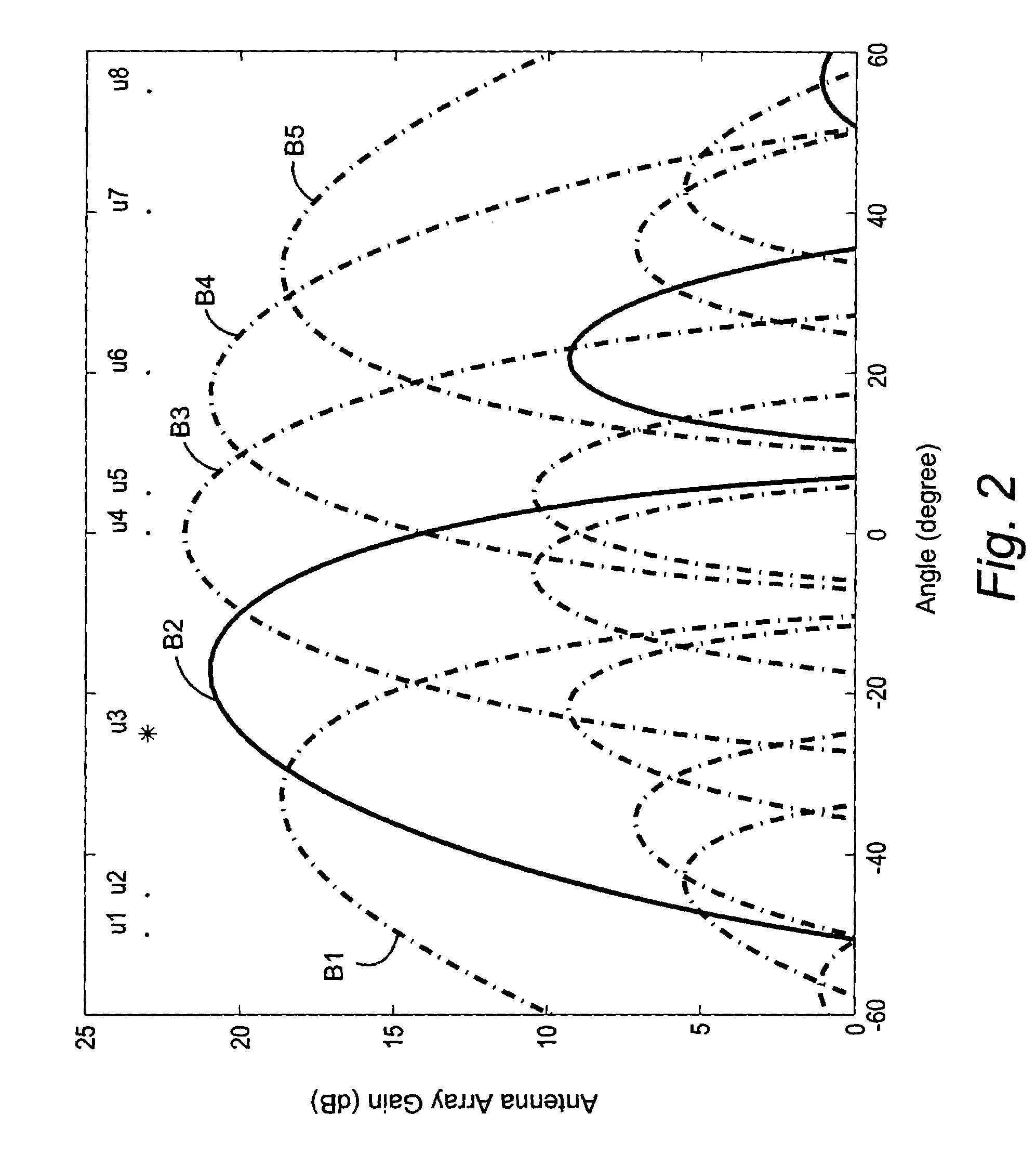
[0008]In the example shown in FIG. 3, the next-scheduled mobile radio is U5 because at the time the scheduling decision was made, U5 had the highest CQI. Beam 3 B3, which encompasses mobile U5, is selected based on beam quality information detected at the base station. At the time instant shown FIG. 2, mobile radio U5 is at a “null” between the main lobe of beam B2 and a side lobe of beam B2. That null means U5 experiences low interference from the beam B2 transmission. On the other hand, mobile radio U4, which is relatively close to mobile radio U5, reports a much lower CQI because the main lobe of beam B2 creates a high interference at U4 on the order of 15 dB. Since mobile U4 is relatively close to the scheduled mobile U3, it is “blasted” by beam B2 and therefore reports a dramatically lower CQI than mobile U5. Yet, in the absence of the beam B2, the reported CQI from both mobiles U4 and U5 would be approximately the same. These kinds of “blasts” cause the flashlight effect.
[0010]The table illustrates that the scheduled mobile radio does not always have the highest CQI during its scheduled TTI. For example, mobile U1 is scheduled to receive a transmission during TTI 5. Mobile U2, which is served by the same beam B1 as mobile U1, reports a very low CQI of 5 during TTI 5 because it is being temporarily “blasted” by the beam B1 transmission to mobile user U1. As a result, mobile U6 reports the highest CQI and is scheduled for TTI 7. Absent the flashlight effect of transmitting to mobile U1 during TTI 5, mobile U2 would have reported a much higher CQI. Indeed, after the flashlight effect of the beam B1 transmission during TTI's 5 and 6 subsides, mobile U2 reports a channel quality of 20, which is higher than the CQI of 18 reported by the scheduled mobile U6. The rapid and dramatic CQI increase from 4 to 20 for mobile U2 between TTI 6 and TTI 7 demonstrates the flashlight effect of beam B1 on mobile U2. This dramatic and rapid change of reported CQI from one scheduled time interval to the next is the flashlight effect.
[0012]The flashlight effect is overcome by selecting multiple mobile radios to receive a transmission over a shared radio channel during a predetermined transmission time interval. Information is transmitted over the shared radio channel to the multiple mobile radios using multiple antenna beams so that interference from the transmission appears as white additive Gaussian noise in time and in space in the cell. The “flashlight effect” caused by a single beam transmission over the shared channel that would detrimentally impact a mobile radio's detection of channel quality is avoided.
[0016]The flashlight effect may be avoided by carefully planning in space and / or in time which beam is used for transmission. Another technique for avoiding the flashlight effect employs a beam transmission sequence order. Multiple mobile radios may be selected to receive a transmission over a shared radio channel using a beam transmission sequence order. Mobile users belonging to a selected beam may be scheduled. The beam selection is decided using a beam sequence number. Information is transmitted over the shared radio channel to each of the mobile radios in the cell following the beam transmission sequence order. Beam switching in accordance with the beam transmission sequence order occurs over multiple transmission time intervals so that interference from the transmission appears as white noise in time and in space.

Problems solved by technology

There is an inherent time delay between the time instant when a mobile user reports the CQI and the time instant that the base station schedules transmission over the high speed shared channel to a mobile user.
If the difference between the reported channel quality and the actual channel quality at the time of scheduling is large, the selected coding and modulation scheme may not be sufficiently robust to ensure transmission with a low enough error rate.
If the data is received in error, the mobile radio requests retransmission which degrades system performance.
This difference between a reported CQI and the actual CQI at the scheduled HS-DSCH transmission is particularly problematic in adaptive antenna systems.
The flashlight effect is a serious problem in fixed multi-beam systems, adaptive antenna systems, and transmit diversity systems.

Method used


Image

  • Reducing shared downlink radio channel interference by transmitting to multiple mobiles using multiple antenna beams
  • Reducing shared downlink radio channel interference by transmitting to multiple mobiles using multiple antenna beams
  • Reducing shared downlink radio channel interference by transmitting to multiple mobiles using multiple antenna beams

Examples


Embodiment Construction

[0027]The following description, for purposes of explanation and not limitation, sets forth specific details, such as particular components, electronic circuitry, techniques, etc., in order to provide an understanding of the present invention. But it will be apparent to one skilled in the art that the present invention may be practiced in other embodiments that depart from these specific details. In other instances, detailed descriptions of well-known methods, devices, and techniques, etc., are omitted so as not to obscure the description with unnecessary detail. Individual function blocks are shown in one or more figures. Those skilled in the art will appreciate that functions may be implemented using discrete components or multi-function hardware. Processing functions may be implemented using a programmed microprocessor or general-purpose computer, using an application specific integrated circuit (ASIC), and / or using one or more digital signal processors (DSPs).

[0028]A shared chan...


PUM


Abstract

A radio base station includes multiple antennas associated with a cell. Multiple mobile radios are selected to receive transmissions over a shared radio channel during a predetermined time interval. Information is transmitted over the shared radio channel to multiple mobile radios in the cell during the predetermined time interval using multiple antenna beams. As a result, interference from the transmission appears as white additive Gaussian noise in time and in space in the cell. A “flashlight effect” caused by a single beam transmission over the shared channel during a predetermined time interval that would normally detrimentally impact mobile channel quality detection is avoided. Other methods for avoiding the flashlight effect are described.

Description

BACKGROUND AND SUMMARY OF THE INVENTION[0001]The present invention relates to cellular radio communications, and more particularly, to downlink radio transmission where multiple antennas are employed at the radio base station.[0002]Shared downlink radio channels, like the high speed-downlink shared channel (HS-DSCH) employed in third generation, wideband code division multiple access (WCDMA) systems, offer high data transmission rates, reduced round-trip delays, and high capacity, at least with respect to a typical transport channel. The HS-DSCH supports higher order modulation to achieve higher user and system throughput, fast link adaptation that takes into account the instantaneous quality of the radio propagation environment and adapts the coding and modulation scheme accordingly, and hybrid-ARQ with soft combining to decrease retransmissions and thereby reduce delay.[0003]HS-DSCH mobile radio users periodically measure the instantaneous radio channel quality of a pilot channel ...

Claims


Application Information

Patent Timeline
Patent Type & Authority Patents(United States)
IPC IPC(8): H04Q7/20H04B7/04H04B7/06H04L12/56H04W16/28H04W72/08H04W72/12
CPCH04B7/0408H04W72/1231H04B7/0617H04B7/0619H04W16/28H04W72/542
Inventor OSSEIRAN, AFIFLOGOTHETIS, ANDREWERICSON, MARTEN
Owner TELEFON AB LM ERICSSON (PUBL)
Why Eureka
Try Eureka