System and method for backpressure compensation for controlling exhaust gas particulate emissions

a technology of backpressure compensation and exhaust gas, which is applied in the direction of electrical control, process and machine control, etc., can solve the problems of reducing engine performance, exhaust backpressure can increase to a point where the life of engine components can be jeopardized, and the engine can be shortened. , to achieve the effect of avoiding unnecessary over-close, increasing turbo speed, and increasing backpressur

Inactive Publication Date: 2008-10-21
DETROIT DIESEL CORP
View PDF21 Cites 32 Cited by
  • Summary
  • Abstract
  • Description
  • Claims
  • Application Information

AI Technical Summary

Benefits of technology

[0011]The VGT vanes are closed to compensate for the loss of air mass flow with increase in backpressure. The VGT vanes closure stops when the rate of change of airflow is decreasing, thereby avoiding unnecessary over closure and increase in turbo speed.

Problems solved by technology

The increasing restriction causes a gradual increase in exhaust (or engine) backpressure (i.e., the pressure within the exhaust upstream of the DPF) causing reduced engine performance.
When the DPF is not properly maintained or when engine conditions prevent the DPF from being regenerated, the exhaust backpressure can increase to a point where engine component life can be jeopardized.
A spiraling of black smoke from the engine exhaust and failure of the DPF can result.

Method used


Image

  • System and method for backpressure compensation for controlling exhaust gas particulate emissions
  • System and method for backpressure compensation for controlling exhaust gas particulate emissions
  • System and method for backpressure compensation for controlling exhaust gas particulate emissions

Examples


Embodiment Construction

)

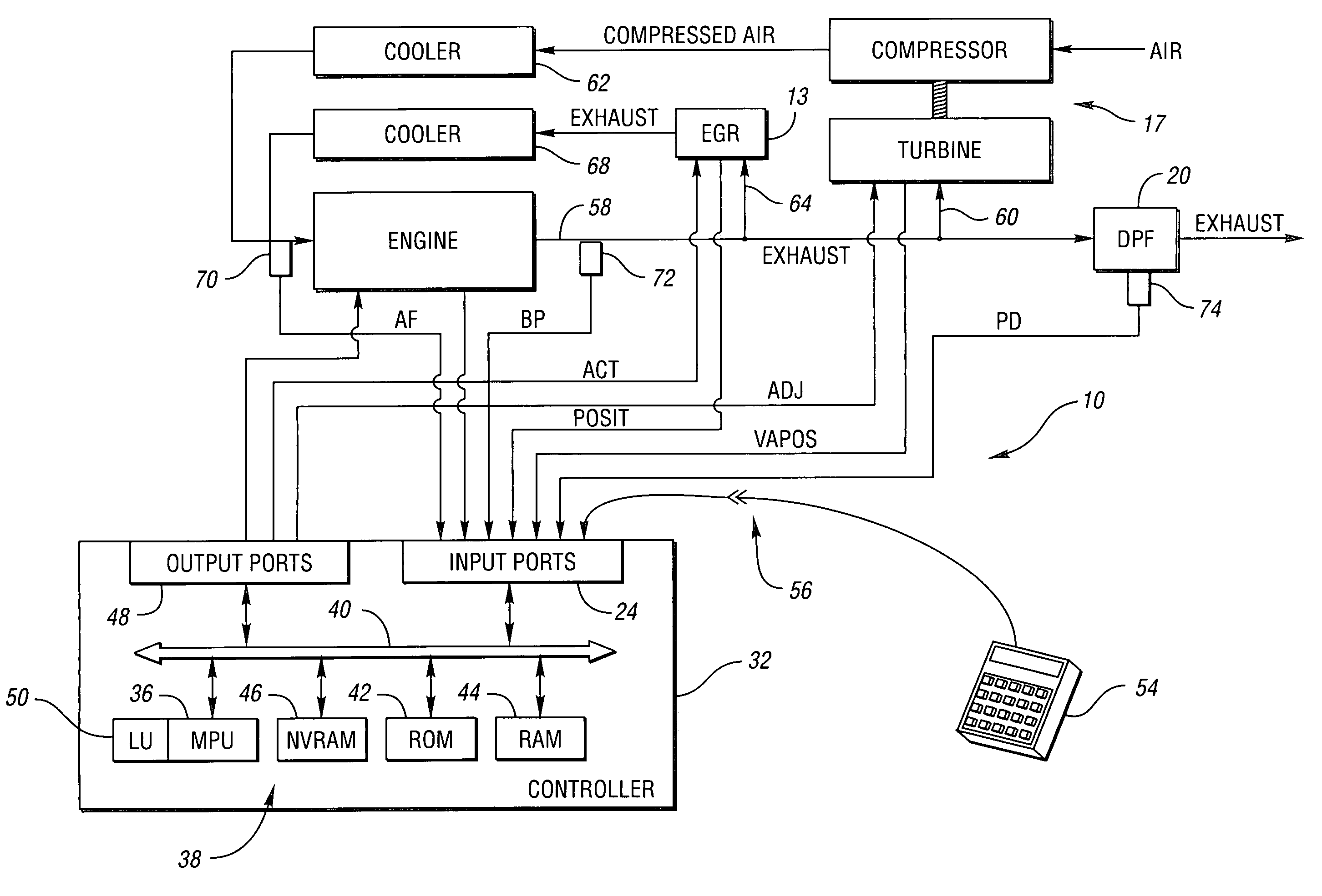
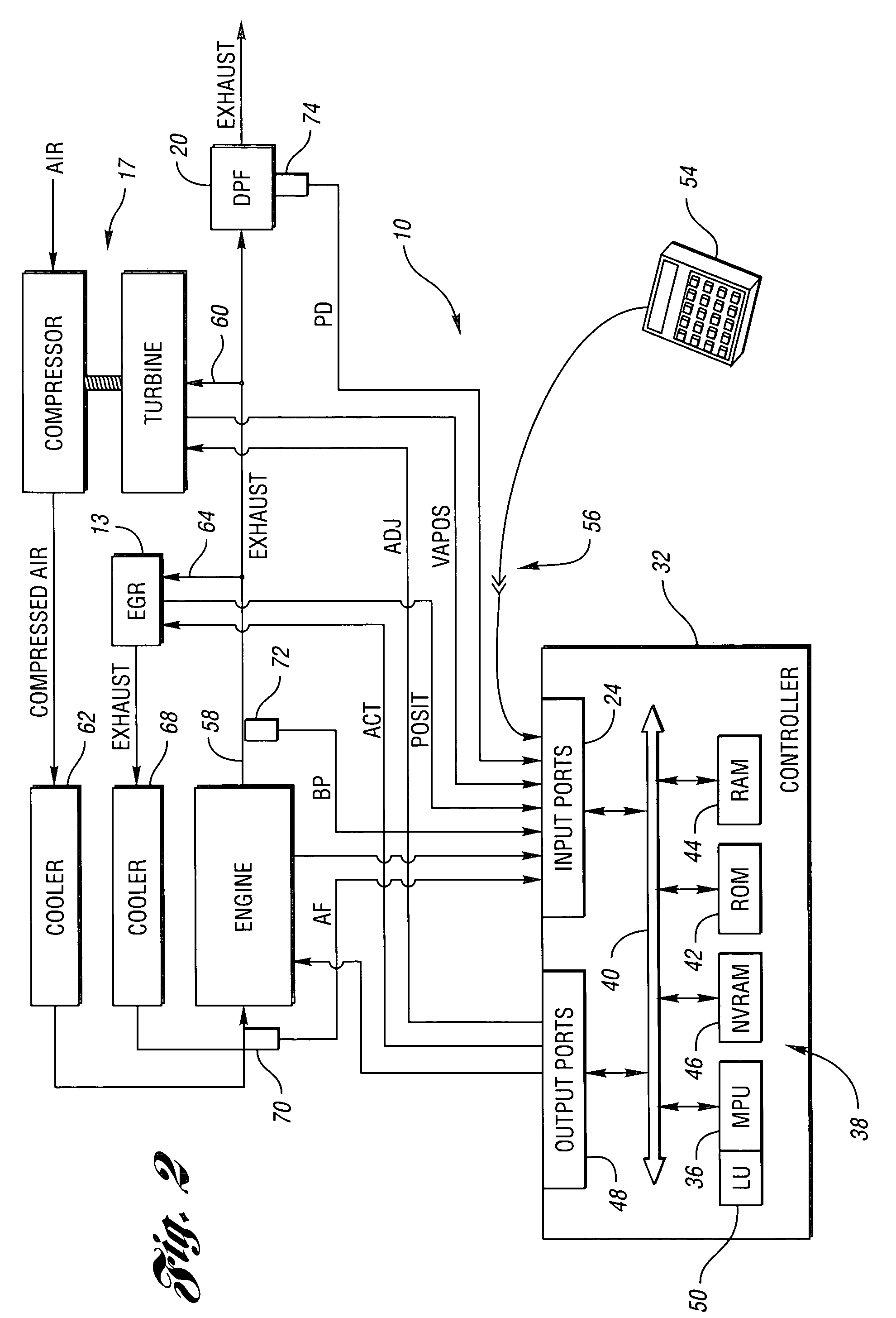
[0018]With reference to the Figures, the preferred embodiments of the present invention will now be described in detail. Generally, the present invention provides an improved system and an improved method for continuously controlling exhaust gas particulate emissions from a compression ignition internal combustion engine. The present invention generally implements continuous backpressure compensation present invention generally provides for calibrating limits on the amount of air flow increase and the amount of exhaust gas recirculation (EGR) flow decrease to provide substantially the same exhaust gas particulate emissions during steady state and transitional modes of operation of the engine.

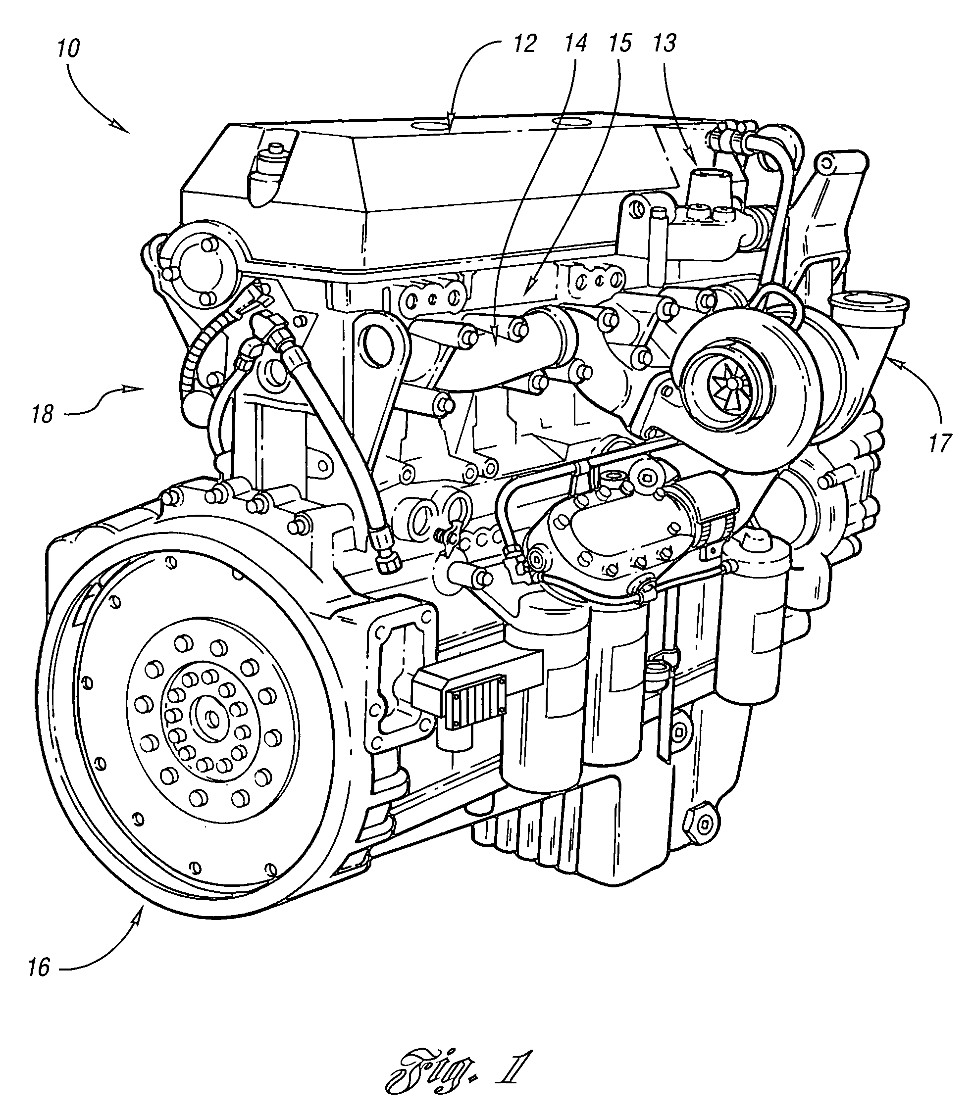
[0019]The present invention is generally implemented in connection with an internal combustion engine (e.g., a compression ignition or diesel engine) having an EGR system, a variable geometry turbine turbocharger (VGT), and an exhaust system having a diesel particulate filter (DPF). An EGR syst...


PUM


Abstract

A method for controlling exhaust gas particulate emissions from a compression ignition internal combustion engine having a variable geometry turbocharger (VGT) includes the steps of determining backpressure across the engine and air mass flow into the engine, closing vanes of the VGT to provide air mass flow increase when backpressure is increasing, and stopping the step of closing the vanes of the VGT when a decrease in rate of change of air mass flow is determined.

Description

BACKGROUND OF THE INVENTION[0001]1. Field of the Invention[0002]The present invention relates to a system and a method for controlling exhaust gas particulate emissions from a compression ignition internal combustion engine.[0003]2. Background Art[0004]Internal combustion engines, and in particular, compression ignition (or diesel) engines have a wide variety of applications including passenger vehicles, marine vessels, earth-moving and construction equipment, stationary generators, and on-highway trucks, among others. Diesel particulate trap or filter (DPFs) have been introduced into the exhaust systems for compression ignition internal combustion engines to reduce particulate emissions (PMs) that are emitted by the engine. Improved systems and methods of reducing PMs are desirable for compression ignition internal combustion engines to meet increasingly stringent emissions standards.[0005]A DPF is an emission control device placed in the exhaust stream to reduce PMs, which are pri...

Claims


Application Information

Patent Timeline
Patent Type & Authority Patents(United States)
IPC IPC(8): F02D23/00F01N3/00F01N3/10F02B33/44F02M25/07G06F17/00G06F19/00
CPCF02B37/22F02D23/00F02D41/0007F02D41/005F02D41/1448F02D41/18F02M25/0754F02B29/0493F02M25/0718F02M25/0738Y02T10/144Y02T10/47F02M26/15F02M26/33F02M26/47Y02T10/12Y02T10/40F02B37/24
Inventor RAMAMURTHY, RAVISHANKARVADUVA, LAURENTIUKREJO, ADMIR
Owner DETROIT DIESEL CORP
Why Eureka
Try Eureka