Magnetic flow probe

a technology of magnetic flow and probe head, which is applied in the direction of electromagnetic flowmeter, volume/mass flow, measurement device, etc., can solve the problems of non-linear response or mechanical failure, fluid flow distribution in the neighborhood of the electrodes may not remain uniform, and the probe head vibrates, etc., to reduce the shunting effect on the flow generated electrode voltage, suppress the vibration of the probe head, and increase the total grounding area

Inactive Publication Date: 2008-10-21
ONICON INC
View PDF4 Cites 9 Cited by
  • Summary
  • Abstract
  • Description
  • Claims
  • Application Information

AI Technical Summary

Benefits of technology

[0011]When a surface of each plate distal from the electrodes is made electrically conductive and is electrically grounded, the plates provide a substantial amount of surface area for electrically grounding the fluid. That area is particularly effective because it is not localized. When the electrical connections between the plates and stem, or other grounding connections, are exposed to the fluid, the total grounding area is increased further. The plate surfaces adjacent the electrodes may be electrically insulated to minimize the shunting effect on the flow generated electrode voltages.
[0012]Yet another aspect of some embodiments of the present invention is that they provide a flow plate structure operable to suppress vibrations of the probe head. The flow obstruction offered by the probe head and stem, characteristic of a bluff body, typically produces vortices that tend to vibrate the stem perpendicular to a plane defined by the flow & the stem. Providing an extended paddle-like face aligned with the flow inhibits this process. The provision of end plates further inhibits vibration by straightening the fluid flow streamlines, capturing flow near the electrodes, and coupling the head more tightly to the fluid.

Problems solved by technology

A concern with flow probes in general is that a non-uniform fluid flow distribution, as may be caused by the flow impedance of the probe head, can cause the probe to vibrate.
This vibration may lead to non-linear response or to mechanical failure.
A particular concern related to magnetic flow probes has been that fluid flow distribution in the neighborhood of the electrodes may not remain uniform because of the flow obstruction caused by the probe itself.
This can result in a nonlinear relation between the flow-generated electrode signal and the flow rate even in the absence of perceptible vibration.
Additional nonlinearities due to the proximity of the pipe wall to the head may also occur.
In these cases the electrically conductive area available for grounding the probe to the fluid may be limited to the stem portion of the probe.
Unless such a probe is used in a relatively small diameter metallic pipe, this lack of grounding can lead to unstable and noisy operation.

Method used


Image

  • Magnetic flow probe
  • Magnetic flow probe
  • Magnetic flow probe

Examples


Embodiment Construction

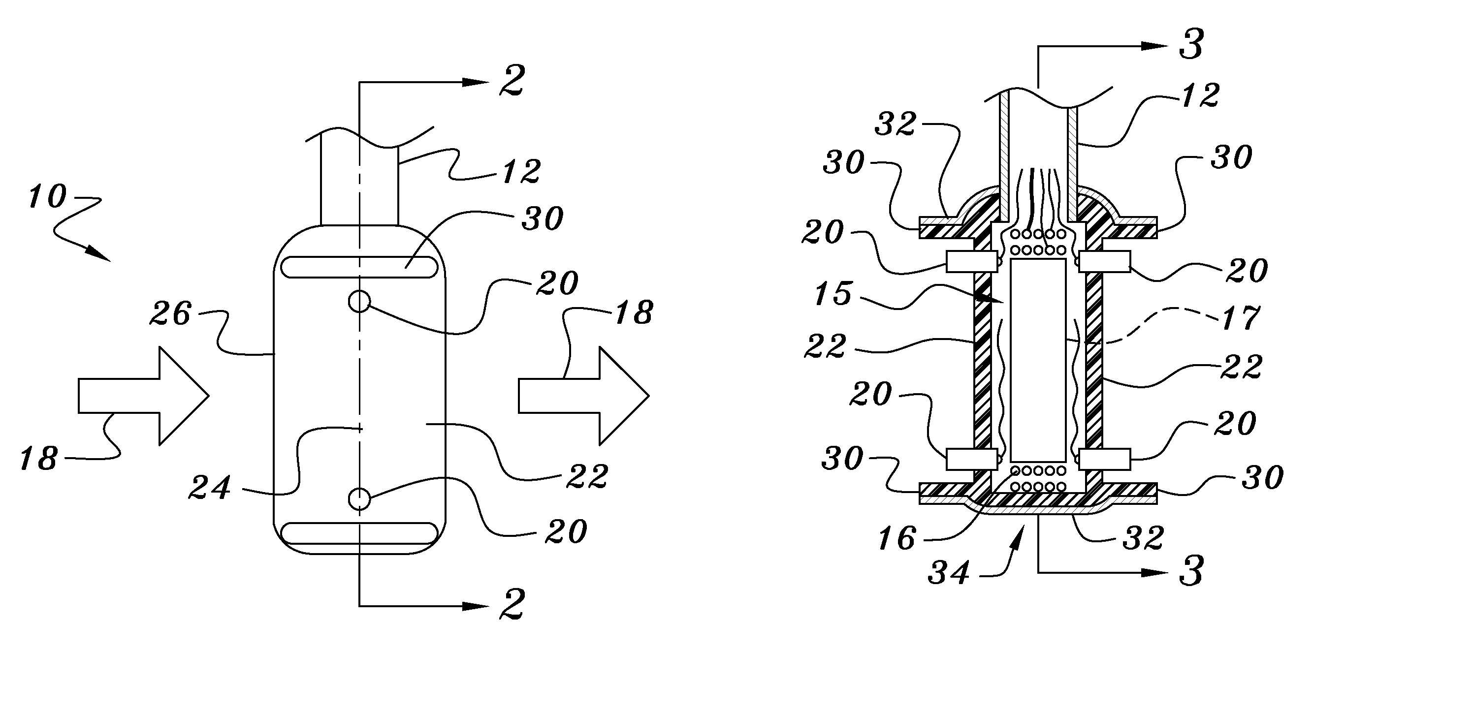
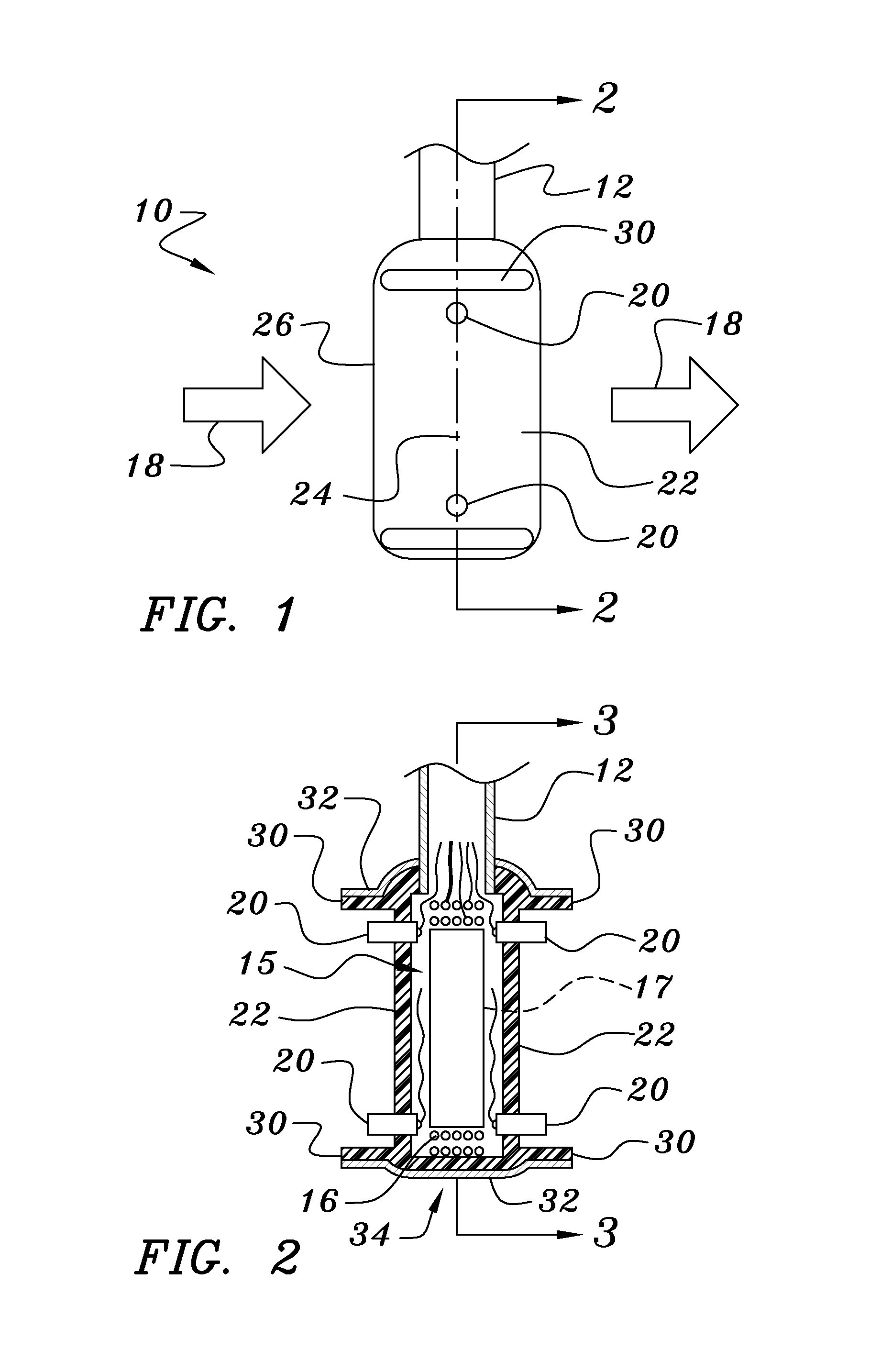
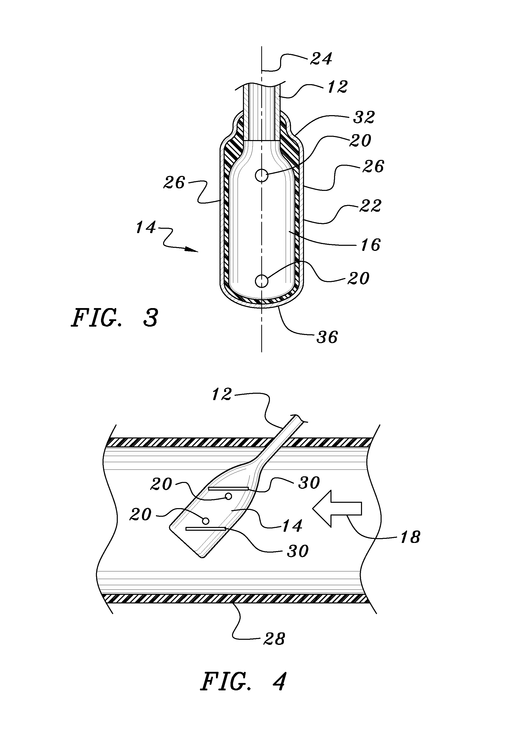
[0018]In studying this Detailed Description, the reader may be aided by noting definitions of certain words and phrases used throughout this patent document. Wherever those definitions are provided, those of ordinary skill in the art should understand that in many, if not most instances, such definitions apply to both preceding and following uses of such defined words and phrases. At the outset of the description, it may be noted that the term ‘paddle-shaped’ and paddle-like refer to a shape analogous to an oar or single-ended canoe paddle comprising a shaft or stem having a blade-like head at one end thereof. In this usage, the term ‘blade-like’ implies a shape having two faces that may be flat or lenticular, that extend along an axis of a probe stem and that are oriented parallel to a flow direction when the sensor is in use. The blade-like shape further implies the presence of leading and trailing edge portions, which may have a minimal extent or which may be nearly as wide as th...


PUM


Abstract

Problems of instability and non-linearity in probe-type magnetic flow meters are ameliorated by either or both of a conductor coating connecting a tip portion of the probe with a supporting probe stem and flat end plates parallel to the flow direction that are arranged adjacent to the sensing electrodes and that act to straighten and confine fluid flowing past the electrodes.

Description

BACKGROUND OF THE INVENTION[0001]1. Field of the Invention[0002]This invention relates to magnetic flow sensing probes used in electromagnetic, or Faraday, flow meters.[0003]2. Background Information[0004]The rate of flow of a conductive fluid can be determined by measuring an electrical potential difference developed in the fluid as the fluid moves through a magnetic field. The potential difference is sensed by at least one pair of electrodes contacting the liquid and spaced apart from each other along a line that is nominally orthogonal to both the direction in which the flow is being measured and a magnetic field produced by a magnet. Some instruments of this sort are configured as in-line flow meters in which the electrodes and magnets are either built into or are very close to the wall of a pipe through which the fluid flows. Other instruments of this type are configured as insertion probes in which the electrodes are or adjacent a free end of the probe. When the probe is inser...

Claims


Application Information

Patent Timeline
Patent Type & Authority Patents(United States)
IPC IPC(8): G01F1/58
CPCG01F1/584G01F1/586
Inventor FELLER, MURRAY F
Owner ONICON INC
Why Eureka
Try Eureka