
Filter element and method of making

a filter element and filter technology, applied in the field of filter elements, can solve the problems of compromising the efficiency of the filter and perhaps even forfeiting its usefulness, and achieve the effect of longer life and higher efficiency

Inactive Publication Date: 2008-10-21
PARKER INTANGIBLES LLC
View PDF35 Cites 25 Cited by
  • Summary
  • Abstract
  • Description
  • Claims
  • Application Information

AI Technical Summary

Benefits of technology

[0009]The present invention provides a filter element that can be constructed to not only meet the recommended microfilter specifications of the Institute of Petroleum, but to also have a longer life and higher efficiency than conventional aviation fuel microfilters satisfying these specifications.
[0010]Particularly, the present invention provides a unique exoskeleton pleat support structure which eliminates the need for cellulose-fiber layers in the pleated media. By eliminating conventional endoskeleton support layers, an increased pleat density is possible which translates into a higher contaminant removal efficiency. Also, a cellulose-fiber-free filter composition eliminates the moisture related problems (e.g., fiber swelling and subsequent pleat deformation) which are associated with cellulose fibers and which are known to dramatically reduce filter life.
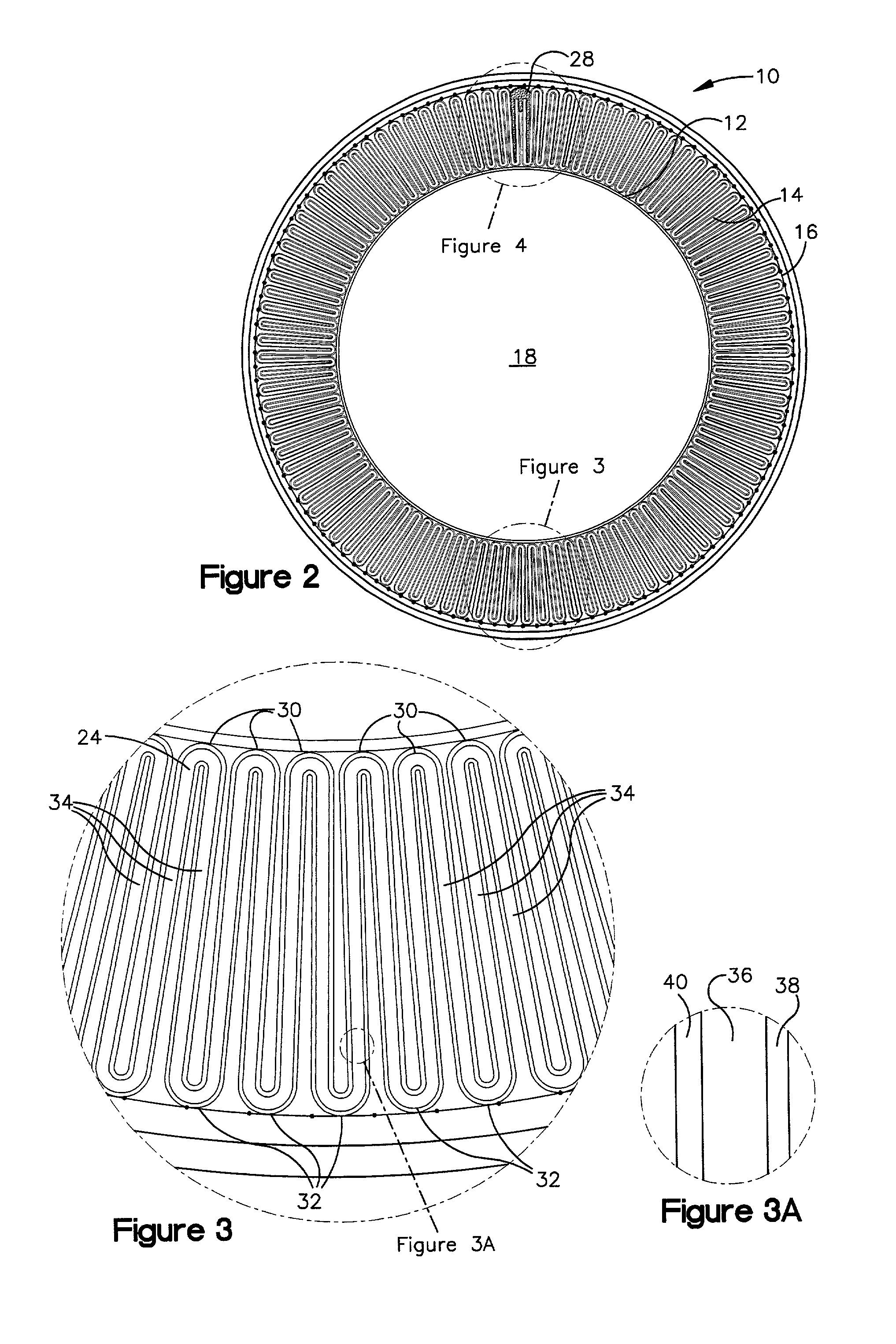
[0013]The support screen can be formed from a flexible thermal-bondable mesh material (PVC-coated fiberglass) whereby it can be non-adhesively attached to the filter pleats by thermal bonding. This construction allows for easy assembly of the support screen by wrapping an appropriately sized sheet of screen material around the filter media and then thermally bonding the screen material to the radially-outer peaks to form the support screen. Also, a side seam can be easily formed for the support screen by thermally bonding overlapping lateral edges of the sheet during this same process.
[0014]According to another aspect of the present invention, there is provided an improved seam construction for a filter media that enhances efficiency and structural integrity of the filter element. Instead of only attaching or bonding certain layers of end pleats in the filter media, the present invention includes all of the relevant layers in the adhesive seam. This minimizes the potential for both interlayer and inter-wall leakage.

Problems solved by technology

Any rips or tears in this seam provide bypass flow passages for the fluid thereby compromising the filter's efficiency and perhaps even forfeiting its usefulness.

Method used


Image

  • Filter element and method of making
  • Filter element and method of making
  • Filter element and method of making

Examples


Embodiment Construction

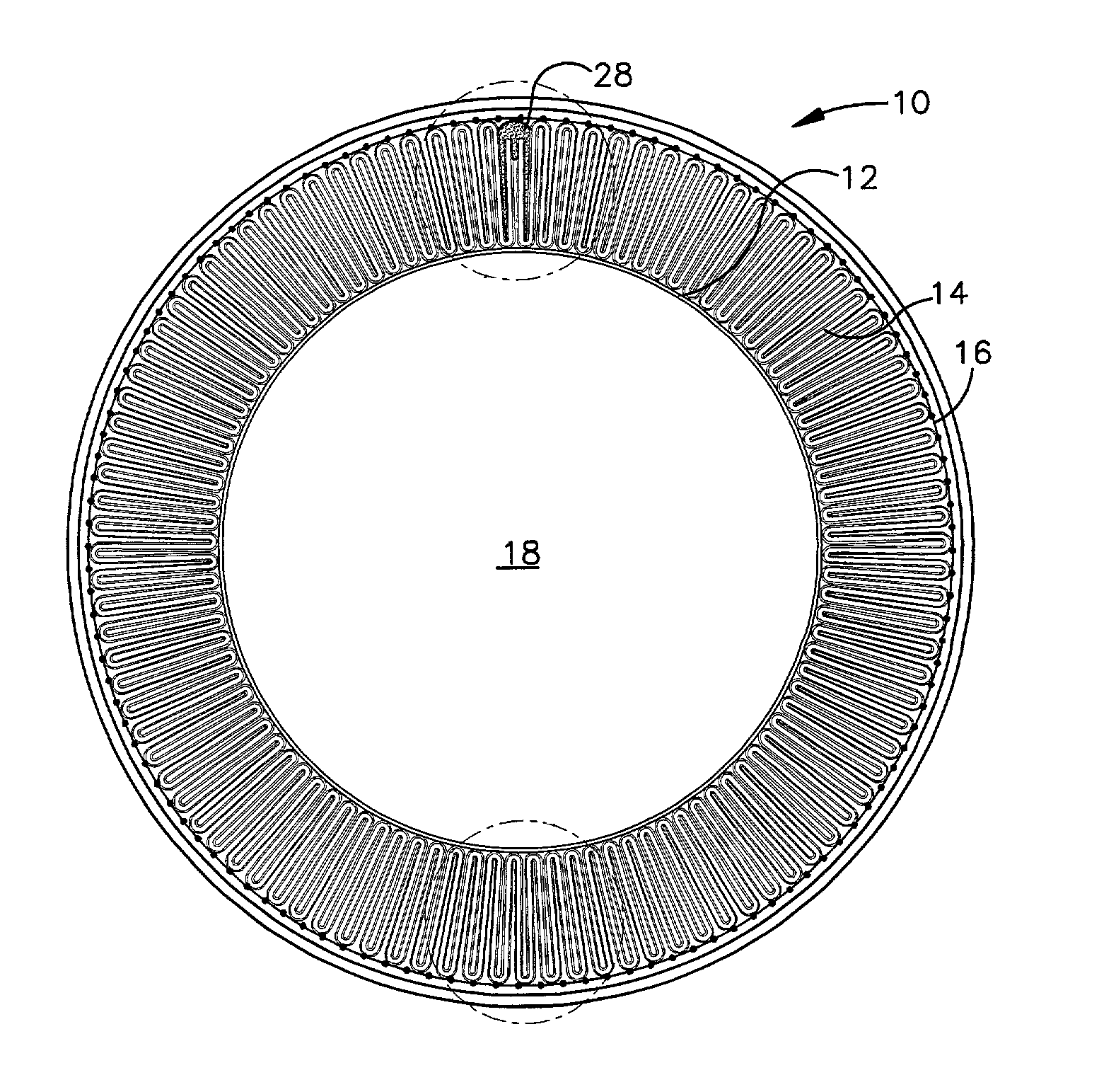
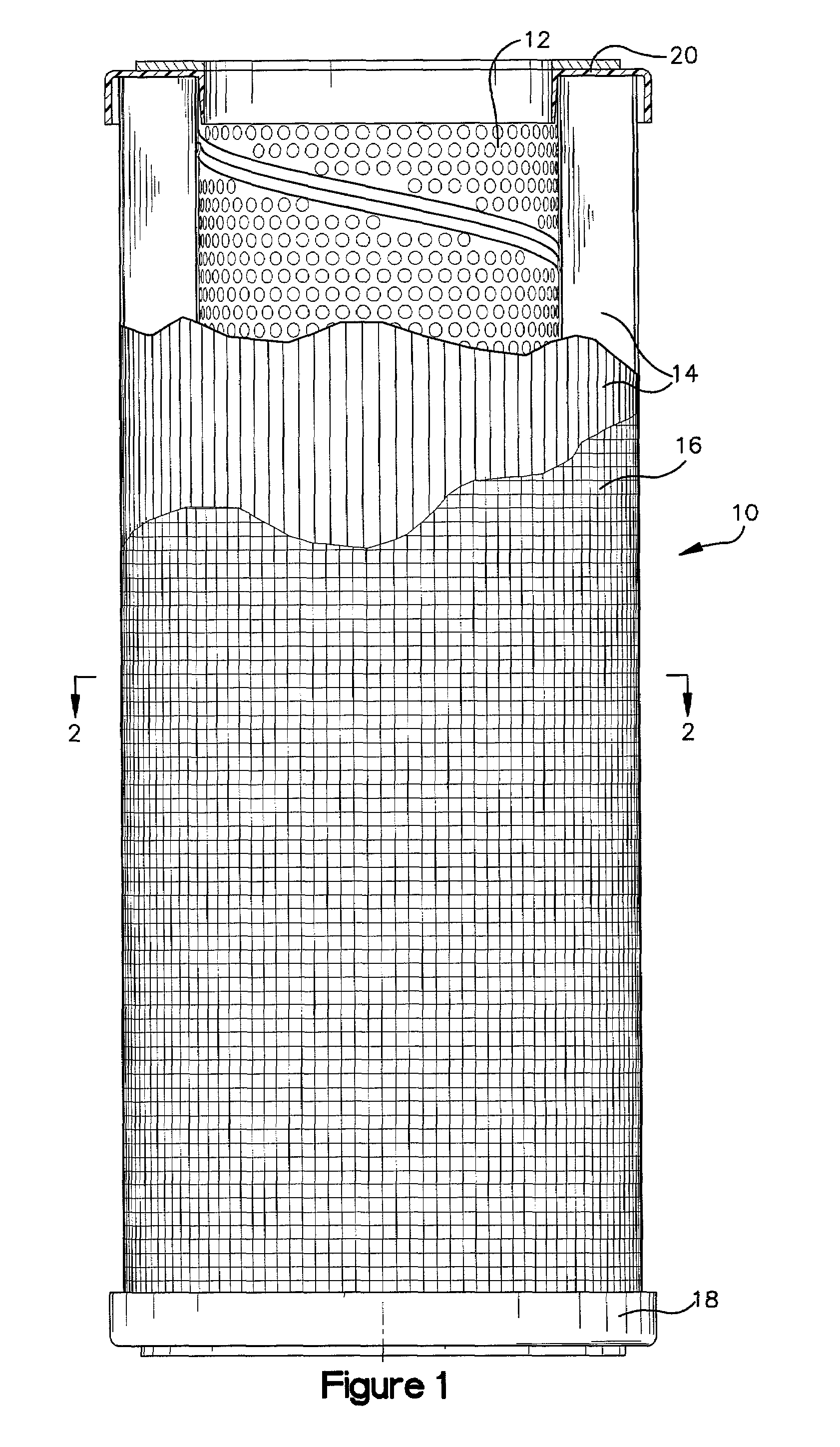
[0027]Referring now to the drawings in detail, and initially to FIGS. 1 and 2, a filter element 10 according to the present invention is shown. The filter element 10 includes a center tube 12, a cylindrical pleated filter media 14 circumscribing the central tube 12, an outer support screen 16, and a pair of end caps 18 and 20. The illustrated filter element 10 can be an aviation fuel microfilter element wherein the fuel flows inwardly through the pleated filter media 14 to continuously remove microsize particles (about 0.5 μm to about 25.0 μm) from the aviation fuel. According to the present invention, such a microfilter element can be constructed to meet and exceed the recommended minimum performance and mechanical specifications of the Institute of Petroleum.

[0028]The center tube 12 preferably has a cylindrical shape and is of an essentially conventional center tube construction. For example, the tube 12 can be made from a sheet of any suitable material, such as perforated steel. ...


PUM

PropertyMeasurementUnit
Lengthaaaaaaaaaa
Lengthaaaaaaaaaa
Lengthaaaaaaaaaa

Abstract

A filter element (10) is provided which can be used to remove microsize contaminant particles (i.e., about 0.5 μm to about 25.0 μm) from aviation fuel. The filter element (10) includes a cylindrical pleated filter media (14) and an exoskeleton support structure (16) supporting the filter media (14). The filter media (14) has a pleat density of about eight to about thirteen pleats per inner diameter inch and is formed only from cellulose-fiber-free and woven-mesh-free layers. The exoskeleton support structure (16) is a screen which is thermally bonded to the pleats' peaks in such a manner that the filter media (14) is sufficiently supported without conventional endoskeleton support layers.

Description

FIELD OF THE INVENTION[0001]The present invention relates generally as indicated to a filter element and, more particularly, to a microfilter element which is constructed to continuously remove microsize impurity particles (e.g., about 0.5 μm to about 25.0 μm) from aviation fuel.BACKGROUND OF THE INVENTION[0002]In a typical filter assembly, a filter element is located within a housing in such a manner that the relevant fluid flows through the filter element and particles are removed therefrom. In one known type of filter element, the filter media comprises a cylindrical construction of pleated material. The filter element can be coreless (i.e., the media's inner radius is self-supporting and received over a support tube integral with the filter housing) or it can include an integral support tube.[0003]A cylindrical pleated filter media is usually made by folding media material into a plurality of longitudinally-extending pleats. The folded media is then shaped into a cylinder with t...

Claims


Application Information

Patent Timeline
IPC IPC(8): B01D27/06B01D17/00B01D29/11B01D36/00
CPCB01D17/00B01D29/111B01D36/003B01D17/045B01D17/10B01D29/21B01D2201/0407B01D2201/0415Y10S210/05
Inventor DENTON, DONALD RAYSMALLWOOD, EDWARD ARTHURO'MEARA, KEVIN SCOTT
Owner PARKER INTANGIBLES LLC
Learn More