
Honeycomb structure and catalytic converter

a technology of honeycomb and catalytic converter, which is applied in the direction of ceramicware, physical/chemical process catalysts, separation processes, etc., can solve the problems of difficult use of compact structure catalytic converters, difficult mounting of catalytic converters, and environmental pollution, so as to prevent the reduction of engine output, increase the cost, and reduce the weight of the vehicl

Active Publication Date: 2008-10-21
NGK INSULATORS LTD
View PDF19 Cites 36 Cited by
  • Summary
  • Abstract
  • Description
  • Claims
  • Application Information

AI Technical Summary

Benefits of technology

The present invention provides a compact catalytic converter with a honeycomb structure that can prevent engine output reduction caused by exhaust gas interference. The invention achieves this by dividing the exhaust gas-incoming and purified gas-outgoing sections of the housing with diaphragms, allowing the two sections to communicate with each other. The honeycomb structure used as the catalyst carrier has standard partition walls and thick partition walls that divide the cells into multiple blocks, and the diaphragms are placed along the thick partition walls. This design allows for effective gas flow and reduces the need for complex exhaust pipe structures or increased vehicle body weight. The invention also provides a holding material between the honeycomb catalyst body and the housing to further improve the communication between the two sections. Overall, the invention provides a compact and effective solution for improving the performance of catalytic converters.

Problems solved by technology

The exhaust gas emitted from an internal combustion engine such as gasoline engine or the like contains a large amount of harmful components such as nitrogen oxide (NOx), hydrocarbons, carbon monoxide and the like.
These harmful components, when per se released into the air, cause environmental pollution; therefore, there is generally mounted, in an exhaust gas passage extending from the internal combustion engine, a catalyst body for purifying the harmful components contained in the exhaust gas.
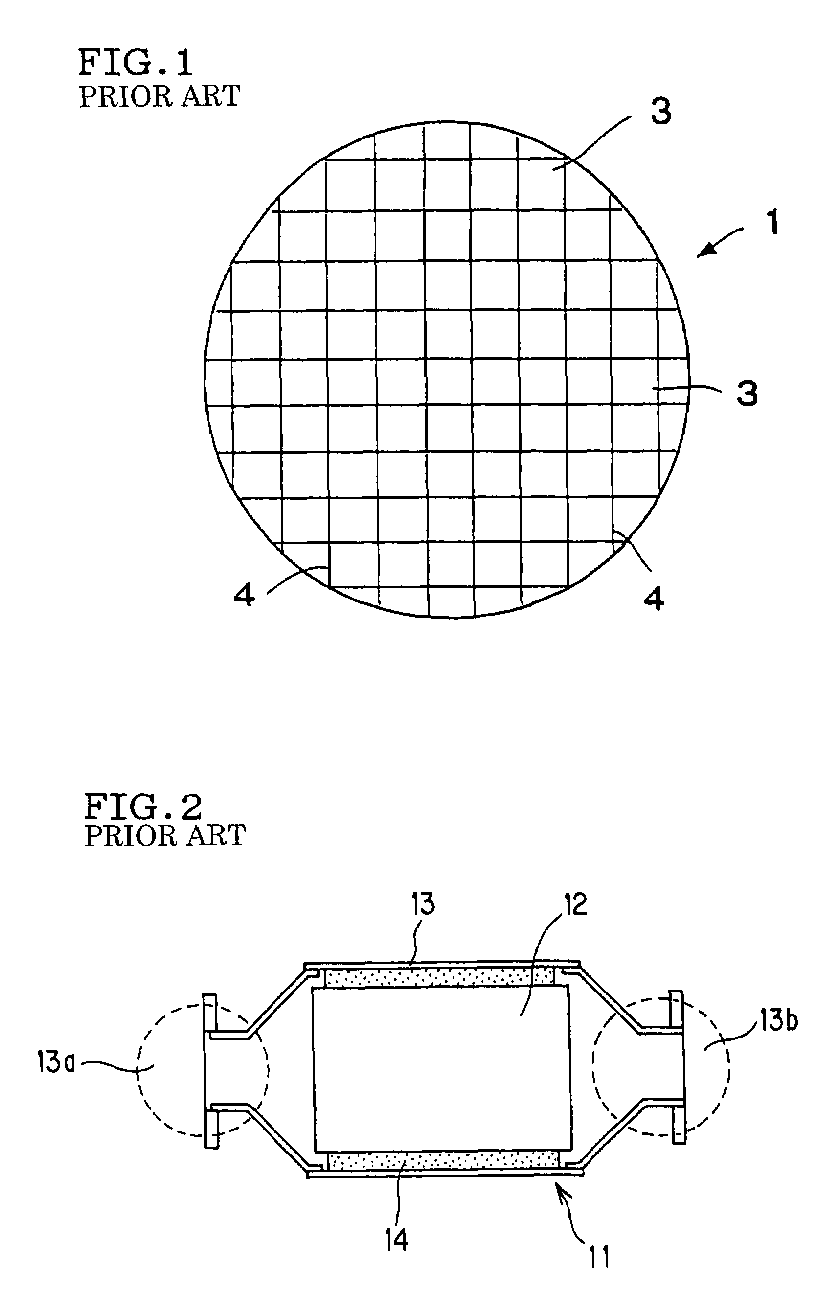
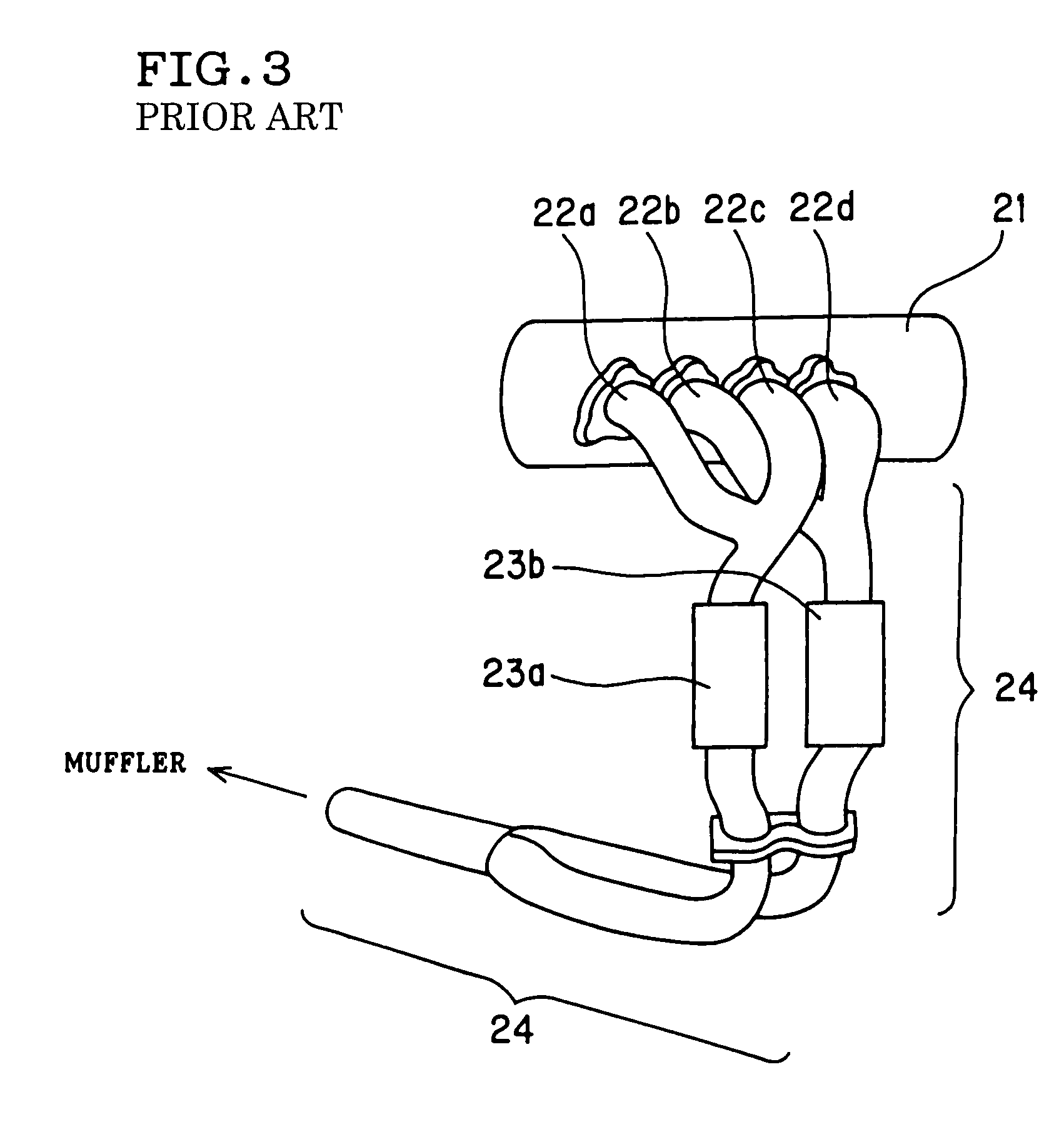
Such a structure is very effective from a standpoint of preventing the reduction in engine output caused by exhaust gas interference; however, this structure requires at least two sets of honeycomb structures as a catalyst carrier, housings (e.g. metal cases) and holding materials (e.g. ceramic mats), making it difficult to use a catalytic converter of compact structure and, when the engine space is small, there has been a case in which mounting of catalytic converter is impossible.
Further, the increase in the number of required parts has invited a complicated exhaust gas structure, an increased weight of vehicle body and an increased cost.

Method used


Image

  • Honeycomb structure and catalytic converter
  • Honeycomb structure and catalytic converter
  • Honeycomb structure and catalytic converter

Examples


example 1

[0151]As the honeycomb structure for constituting a honeycomb catalyst body, there was used a honeycomb structure made of cordierite, which had a circular end face shape of 100 mm in diameter, a length of 100 mm, a square cell shape of 1.27 mm×1.27 mm, a partition wall thickness of 110 μm (4 mil), a cell density of 62 cells / cm2 (400 cells / in.2) and an outer peripheral wall thickness of 0.3 mm and wherein an internal wall 5 of 0.3 mm in thickness, such as shown in FIG. 5(a) and FIG. 5(b) was formed at the central portion. That is, there was used a honeycomb structure wherein a large number of cells were divided by an internal wall into left and right two cell blocks.

example 2

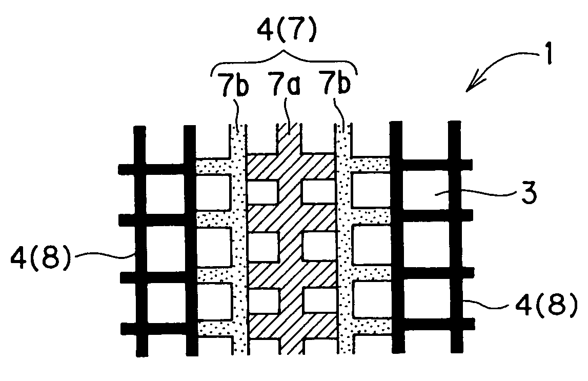
[0152]As the honeycomb structure for constituting a honeycomb catalyst body, there was used a honeycomb structure made of cordierite, which had a circular end face shape of 100 mm in diameter, a length of 100 mm, a square cell shape of 1.27 mm×1.27 mm, a partition wall thickness of 110 μm (4 mil), a cell density of 62 cells / cm2 (400 cells / in.2) and an outer peripheral wall thickness of 0.3 mm and wherein three thick partition walls 7 of 135 μm (5 mil) in thickness, such as shown in FIG. 7(a) and FIG. 7(b) were formed at the central portion. That is, there was used a honeycomb structure wherein a large number of cells were divided by thick partition walls into left and right two cell blocks.

example 3

[0153]As the honeycomb structure for constituting a honeycomb catalyst body, there was used a laminate such as shown in FIG. 13(a) and FIG. 13(b), of a first honeycomb structure 32c made of cordierite, which had a circular end face shape of 100 mm in diameter, a length of 60 mm, a square cell shape of 1.27 mm×1.27 mm, a partition wall thickness of 110 μm (4 mil), a cell density of 62 cells / cm2 (400 cells / in.2) and an outer peripheral wall thickness of 0.3 mm and a second honeycomb structure 32d made of cordierite, which had a circular end face shape of 100 mm in diameter, a length of 20 mm, a square cell shape of 2.54 mm×2.54 mm, a partition wall thickness of 430 μm (17 mil), a cell density of 15.5 cells / cm2 (100 cells / in.2) and an outer peripheral wall thickness of 0.5 mm.

[0154]In lamination of the first honeycomb structure 32c and the second honeycomb structure 32d, the two honeycomb structures were disposed so that the partition walls of the central portions of the two honeycomb ...


PUM

PropertyMeasurementUnit
thicknessaaaaaaaaaa
thicknessaaaaaaaaaa
central angleaaaaaaaaaa

Abstract

A catalytic converter has a honeycomb catalyst body, a housing and a holding material, wherein the honeycomb catalyst body has, as the catalyst carrier, a honeycomb structure having an inner wall(s) which is (are) provided so as to divide the large number of cells into two or more cell blocks and which has (have) a thickness larger than the thickness of the partition walls, and the exhaust gas-incoming section and purified gas-outgoing section of the housing are divided by diaphragms into two or more exhaust gas-incoming passages and two or more purified gas-outgoing passages, and the two or more cell blocks of the honeycomb structure are allowed to communicate with the corresponding two or more exhaust gas-incoming passages and corresponding two or more purified gas-outgoing passages of the housing. This catalytic converter has a compact structure and can effectively prevent the reduction in engine output caused by exhaust gas interference, without adoption of complicated exhaust pipe structure, or increase in vehicle body weight, or increase in cost.

Description

BACKGROUND OF THE INVENTION AND RELATED ART STATEMENT[0001]The present invention relates to a honeycomb structure suitably used as a catalyst carrier in a catalyst body for purifying an exhaust gas emitted from an internal combustion engine such as gasoline engine or the like, as well as to a catalytic converter comprising a honeycomb catalyst body and a housing holding the honeycomb catalyst body.[0002]The exhaust gas emitted from an internal combustion engine such as gasoline engine or the like contains a large amount of harmful components such as nitrogen oxide (NOx), hydrocarbons, carbon monoxide and the like. These harmful components, when per se released into the air, cause environmental pollution; therefore, there is generally mounted, in an exhaust gas passage extending from the internal combustion engine, a catalyst body for purifying the harmful components contained in the exhaust gas.[0003]As the catalyst body used for such a purpose, there can be mentioned, for example, ...

Claims


Application Information

Patent Timeline
Patent Type & Authority Patents(United States)
IPC IPC(8): B01D50/00B01D53/34B01D53/86B01D53/94B01J35/04C04B38/00F01N3/28F01N13/04
CPCB01D53/9454B01J35/04F01N3/2828F01N3/2853F01N13/017F01N3/2892F01N2240/20F01N2330/30Y02T10/22Y02A50/20Y02T10/12B01J35/56
Inventor KATO, YASUSHI
Owner NGK INSULATORS LTD
Learn More