Ion beam irradiation apparatus

a technology of ion beam and irradiation apparatus, which is applied in the direction of optical radiation measurement, instruments, therapy, etc., can solve the problems of non-uniform surface of ion beam b>54/b>, and prevent the density of ion beam applied onto the substrate, so as to improve the uniformity of ion implantation on the surface of the substra

Inactive Publication Date: 2008-10-21
NISSIN ION EQUIP CO LTD
View PDF8 Cites 3 Cited by
  • Summary
  • Abstract
  • Description
  • Claims
  • Application Information

AI Technical Summary

Benefits of technology

[0021]Therefore, it is an object of the invention to prevent, even in case that the substrate is scanned in the tiling state in the irradiation direction of the ion beam, the density of the ion beam applied onto the substrate from becoming non-uniform in the surface of the substrate.
[0029]According to the invention, while the distance from the arbitrary point on the path of the ion beam to the surface of the substrate is kept substantially constant, the substrate held by the holder can be scanned in the tiling state in the irradiation direction of the ion beam. Therefore, the area of the irradiation region of the ion beam applied onto the substrate becomes always substantially constant. Thus, it is possible to prevent the density of the ion beam applied onto the substrate from becoming non-uniform in the surface of the substrate. In result, uniformity of ion implantation in the surface of the substrate improves.

Problems solved by technology

However, in case that the substrate 54, in the tilting state in the irradiation direction Z of the ion beam 58, is scanned in the direction along the Y-axis, there is a problem that the density of the ion beam 58 applied onto the substrate 54 becomes non-uniform in the surface 56 of the substrate 54.

Method used


Image

  • Ion beam irradiation apparatus
  • Ion beam irradiation apparatus
  • Ion beam irradiation apparatus

Examples


Embodiment Construction

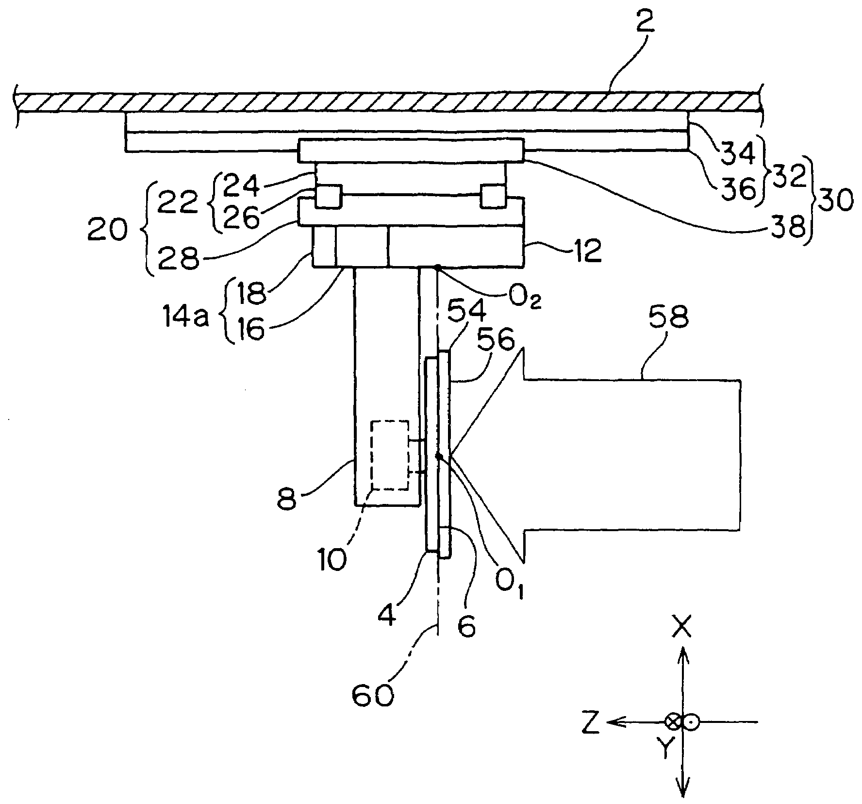
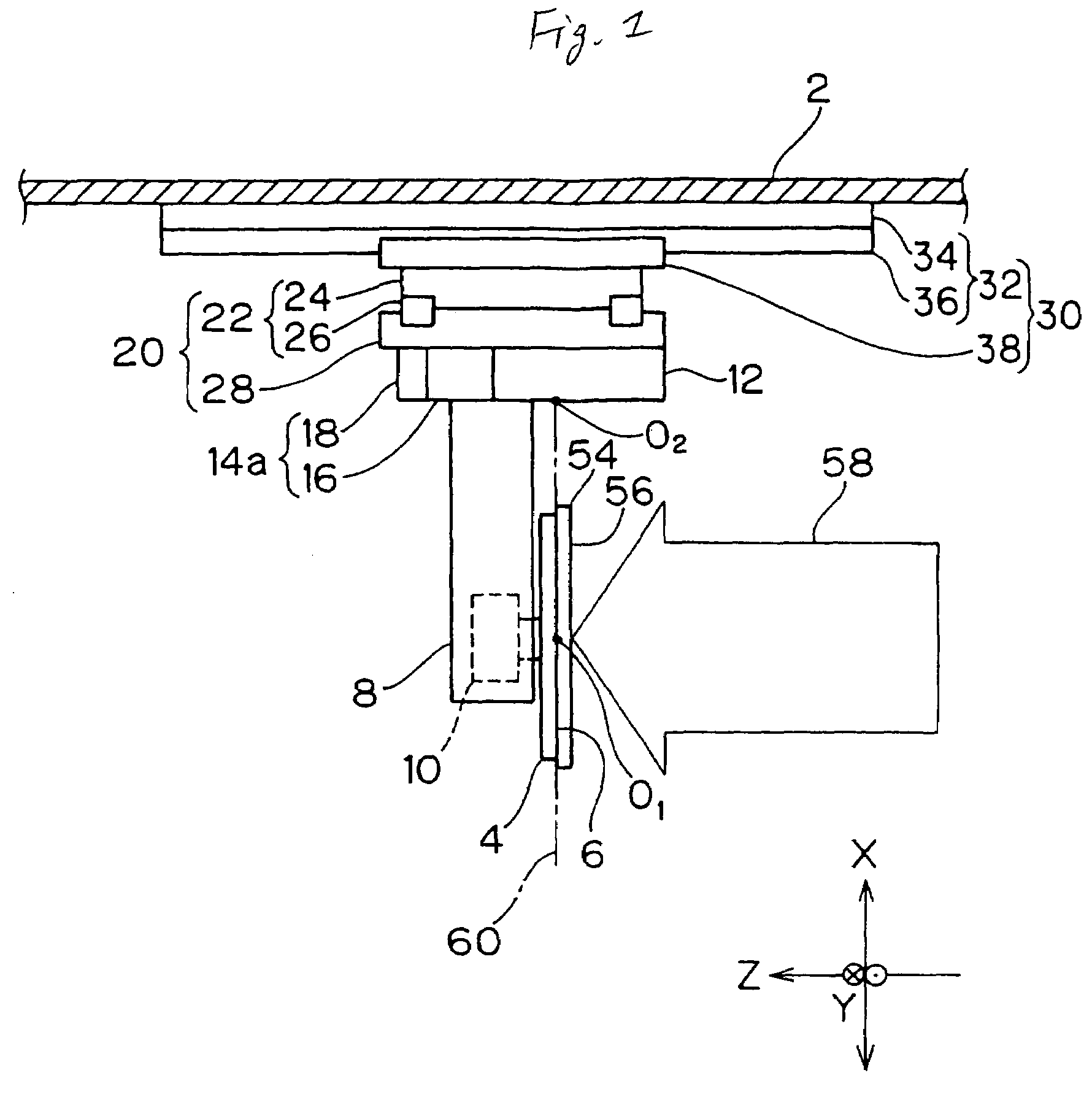
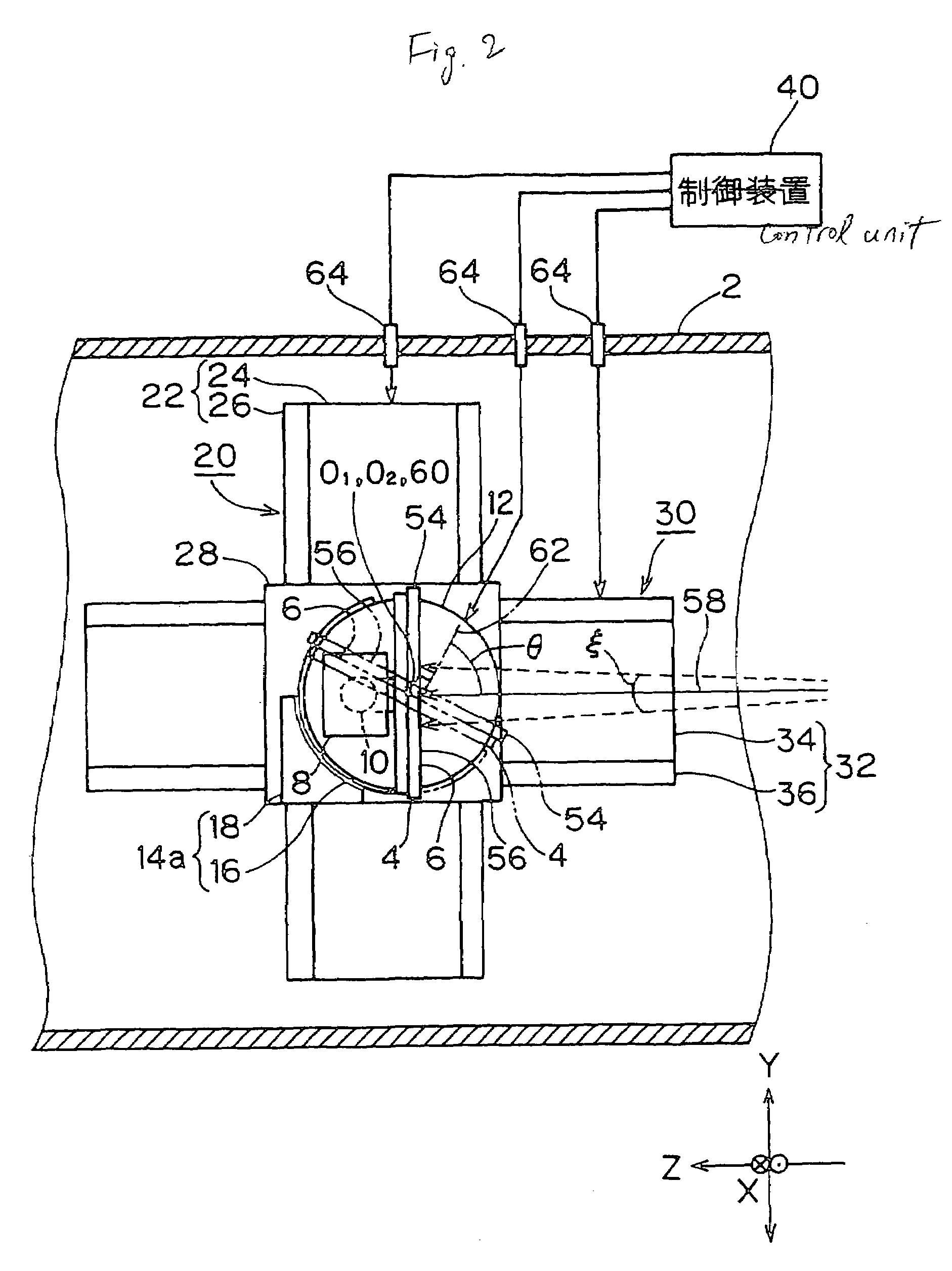
[0035]FIG. 1 is a schematically plan view showing one exemplary, non-limiting example of an ion beam irradiation apparatus according to this invention, and FIG. 2 is a schematically side view of the ion beam irradiation apparatus shown in FIG. 1. The same or corresponding parts as or to those in the related art shown in FIGS. 4 and 5 are denoted by the same reference numerals, and the different points from the related art will be mainly described below.

[0036]In this ion beam irradiation apparatus, an arm 8 for supporting a holder 4 is supported by a disc-shaped turn table 12. At this time, a center O2 of the turn table 12 is on an imaginary center axis 60 that passes through a center O1 of a substrate holding surface 6 of the holder 4 and is substantially parallel to an X-axis (refer to FIG. 1). The shown substrate 54, though it has the same thickness as thickness of the holder 4 for convenience, is very thin actually. Therefore, it can be said that the center axis 60 substantially ...


PUM


Abstract

Three axes that are orthogonal to each other at one point are taken as an X-axis, a Y-axis and a Z-axis. An irradiation angle setting motor holds a holder, and sets an irradiation angle θ of an ion beam by rotating this holder around a center axis that is parallel to the X-axis. A Y-axis linear motor causes the holder and the irradiation angle setting motor to ascend and descent in the direction of the Y-axis. A Z-axis linear motor moves the holder, the irradiation angle setting motor and the Y-axis linear motor in the direction of the Z-axis. A control unit operation-controls synchronously the Y-axis linear motor and the Z-axis linear motor so that a substrate holding surface of the holder reciprocates and scans linearly along an S-axis that is parallel to the substrate holding surface and orthogonal to the X-axis.

Description

[0001]The present application claims foreign priority based on Japanese Patent Application No. 2005-150832, filed May 24, 2005, the content of which is incorporated herein by reference.BACKGROUND OF THE INVENTION[0002]1. Technical Field[0003]The present invention relates to an ion beam irradiation apparatus so constructed as to irradiate a substrate held by a substrate holding surface of a holder with an ion beam that travels in the horizontal direction. Particularly, the invention relates to means for controlling non-uniformity of ion implantation due to a divergent angle of the ion beam applied onto the substrate. This ion beam irradiation apparatus is, for example, an ion implantation apparatus.[0004]2. Related Art[0005]FIG. 4 shows a schematic side view of this type of related-art ion beam irradiation apparatus, showing an example of the constitution in which the substrate held by the holder is irradiated with the ion beam. An ion beam irradiation apparatus having the nearly sim...

Claims


Application Information

Patent Timeline
Patent Type & Authority Patents(United States)
IPC IPC(8): G21K5/10
CPCH01L21/67005H01L21/68H01L21/68764H01J2237/20207H01J2237/20221H01J2237/31701H01L21/265H01J37/20H01J37/3171
Inventor NAKAYA, MAKOTO
Owner NISSIN ION EQUIP CO LTD
Why Eureka
Try Eureka