Constant current biasing circuit for linear power amplifiers

a technology of biasing circuit and linear power amplifier, which is applied in the direction of amplifiers with semiconductor devices/discharge tubes, amplifiers with only semiconductor devices, and gain control, etc., can solve the problems of biasing current fluctuations, diode not creating, and limited dynamic range of biasing curren

Inactive Publication Date: 2008-10-28
SKYWORKS SOLUTIONS INC
View PDF13 Cites 17 Cited by
  • Summary
  • Abstract
  • Description
  • Claims
  • Application Information

AI Technical Summary

Benefits of technology

[0008]An example implementation of a constant current biasing circuit is in a linear amplifier. A biasing voltage results in a biasing current that may then be mirrored as a reference current to the power amplifier. The bias circuit also provides feedback around a reference transistor residing on the power amplifier. This feedback loop maintains a quiescent bias for the reference transistor equal to the reference current. The resulting bias voltage from the feedback loop is then used to bias the RF power device. Since the bias point of the amplifier is controlled and does not vary with temperature, the amplifier exhibits reduced variation in linearity over temperature. As a result, the amplifier benefits from increased design margin.

Problems solved by technology

A disadvantage of using a diode in the biasing circuit is that the diode does not create a linear relationship between the bias voltage and the biasing current.
Additionally, the dynamic range of the biasing current is limited by a resistor diode biasing circuit.
The diode in the resistor diode biasing circuit also results in biasing current fluctuations when the temperature changes.
The biasing current fluctuations have an adverse effect on the circuit being biased and must be tolerated or have additional temperature compensation circuitry added.

Method used


Image

  • Constant current biasing circuit for linear power amplifiers
  • Constant current biasing circuit for linear power amplifiers
  • Constant current biasing circuit for linear power amplifiers

Examples


Embodiment Construction

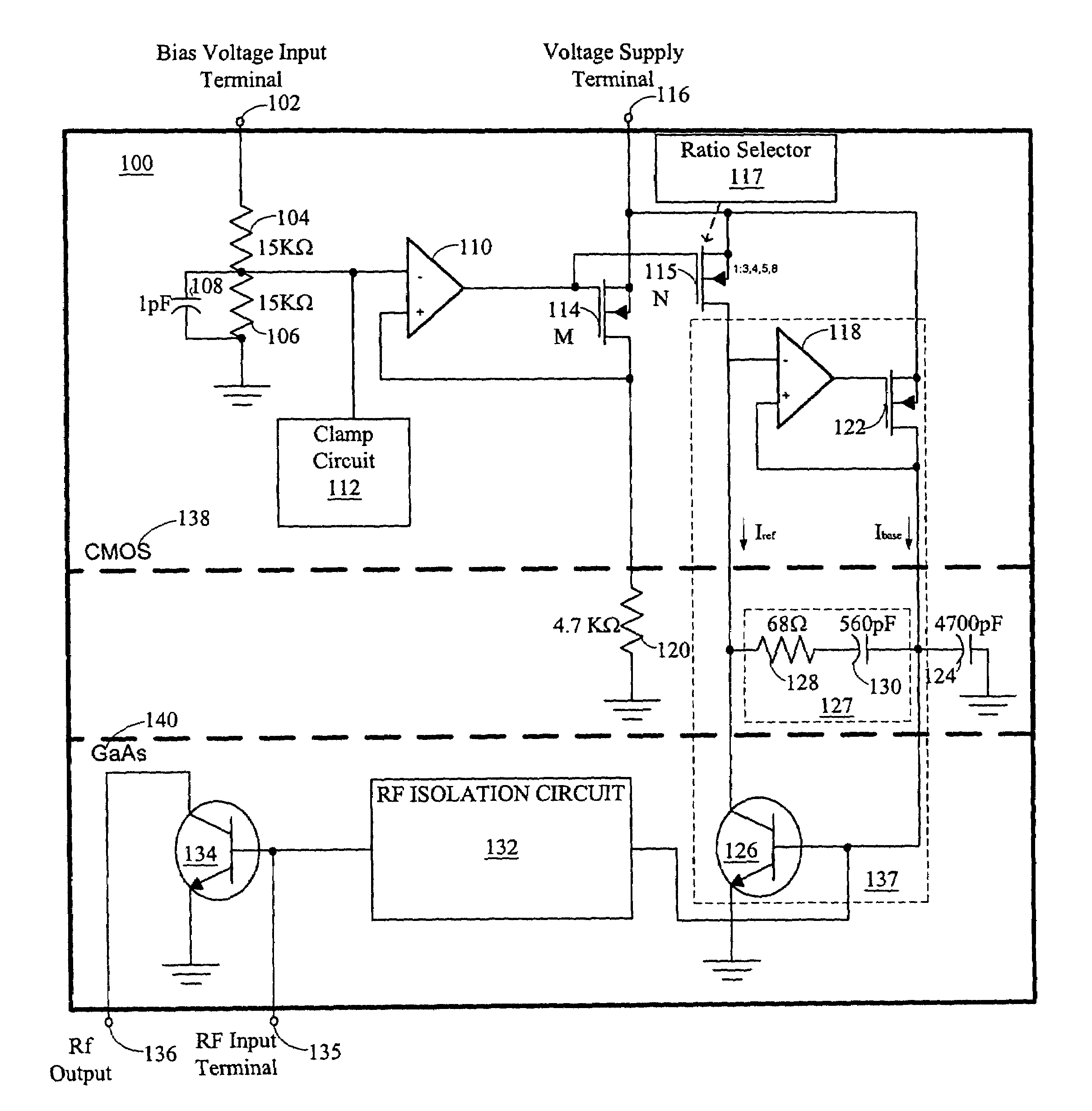
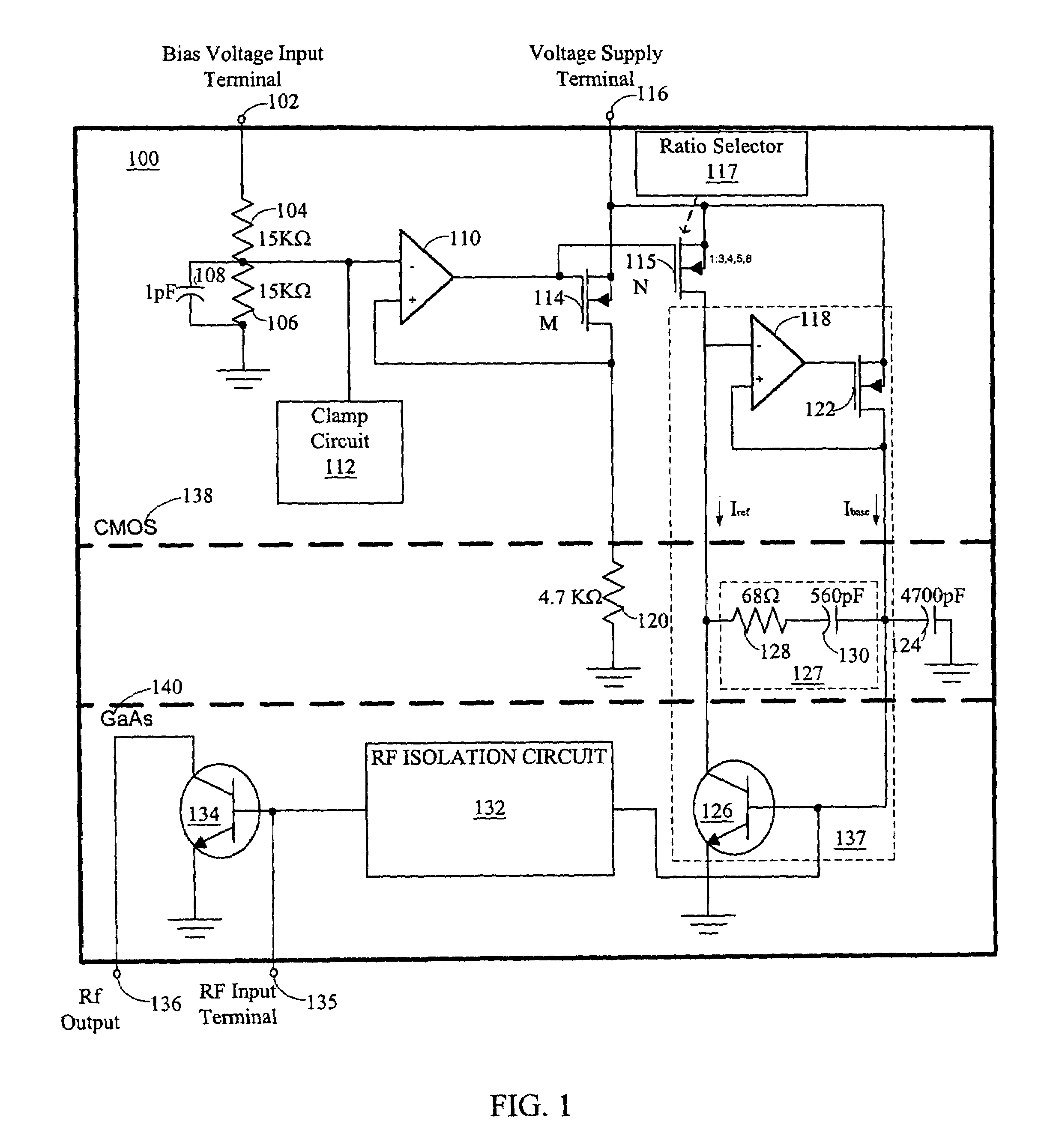
[0014]In FIG. 1, an illustration of a circuit diagram of an exemplary implementation of a single-stage amplifier 100 having a constant current bias circuit is shown. A bias voltage input terminal 102 is connected to a fifteen kilo-ohm resistor 104. Another fifteen kilo-ohm resistor 106 is connected to the fifteen kilo-ohm resistor 104 and a ground. The two fifteen kilo-ohm resistors 104 and 106 are commonly referred to as a voltage divider resistor pair having an output between the fifteen kilo-ohm resistors 104 and 106. A one pico-farad capacitor 108 is connected as a filter across the resistor 106. The output from the voltage divider resistor pair is also connected to the negative input terminal of op-amp 110 and clamp circuit 112.

[0015]The output of the op-amp 110 is connected to the respective gates of a CMOS field effect transistor (FET) 114 and a selectable CMOS FET 115. The CMOS FET 114 has a source that is connected to the voltage supply terminal 116. The CMOS FET 114 has a ...


PUM


Abstract

A constant current bias approach that receives an input bias voltage and maintains a temperature independent constant current bias in a linear amplifier device. Integrated sense circuitry protects against unacceptable input voltages to guarantee bias stability. Fabrication in multiple semiconductor technologies and assembly into a single package allows for optimum cost and performance of DC bias and RF amplifier sections.

Description

CROSS REFERENCE TO RELATED APPLICATION[0001]This application is a continuation of U.S. patent application Ser. No. 09 / 693,398, entitled “CONSTANT CURRENT BIASING CIRCUIT FOR LINEAR POWER AMPLIFIERS,” filed Oct. 21, 2000 now U.S. Pat. No. 6,639,470, and the benefits of that application and of U.S. Provisional Application No. 60 / 238,846, entitled “CONFIGURABLE POWER AMPLIFIER BIAS CONTROL,” filed Oct. 6, 2000, are hereby claimed and the specifications thereof incorporated by reference.BACKGROUND OF THE INVENTION[0002]1. Technical Field[0003]This invention relates generally to biasing circuits and, in particular, to constant current biasing circuits.[0004]2. Related Art[0005]A resistor and a diode are commonly used with a bias voltage to create a biasing current for use in numerous types of circuits including amplifiers. As the bias voltage is applied to the resistor diode biasing circuit, a biasing current results. A disadvantage of using a diode in the biasing circuit is that the dio...

Claims


Application Information

Patent Timeline
Patent Type & Authority Patents(United States)
IPC IPC(8): H03F3/04H03F3/24H03F1/02H03F1/30H03F3/343H03G3/10
CPCH03F1/0261H03F1/302H03F3/343H03F2200/18H03F2200/453H03F2200/513
Inventor ANDRYS, PAULBLOOM, MARKFINLAY, HUGH J.RIPLEY, DAVIDSHIE, TERRYHOHEISEL, KEVIN
Owner SKYWORKS SOLUTIONS INC
Why Eureka
Try Eureka