Apparatus and method for using optical mouse engine to determine speed, direction, position of scanned device and to obtain quantitative or qualitative data from same

a technology of optical mouse engine and lateral flow assay, which is applied in the field of apparatus and method for reading lateral flow assay strips or, can solve the problems of skew test, inability to read test strips for medical test data collection, and inability to determine, so as to achieve high-speed data read rates and sensitivity

Active Publication Date: 2008-10-28
BECTON DICKINSON & CO
View PDF31 Cites 32 Cited by
  • Summary
  • Abstract
  • Description
  • Claims
  • Application Information

AI Technical Summary

Benefits of technology

[0007]In accordance with an aspect of the present invention, an optical engine (e.g., an imager / sensor operating in conjunction with a microcontroller or other processing device) is configured within a reader to determine a current position for a test strip that has been inserted into the reader. Internal self-test and diagnostic monitor algorithms are then performed to ensure that the strip is fully inserted and withdrawn with respect to the reader, and that all data from the reagent lines are within limits. The optical sensor has high speed data read rates and sensitivity to provide both accurate quantification of the reagent stripes on the strip and real-time motion information output as quadrature data. The microcontroller uses the motion information to determine the speed, direction and position of the strip as it is being inserted into and withdrawn from the reader by a user. Since the substantially exact position of the strip is known with respect to the reader, the microcontroller can calculate the optical absorption of each colored reagent line and, similarly, calculate the diagnostic significance (i.e., either qualitative or quantitative) of the scanned device.

Problems solved by technology

This reader and other similar readers, however, can be relatively costly to implement and inaccurate.
The process of inserting a test strip into a reader and removing it therefrom is subject to much variation that can skew test results.
None of these existing optical mouse engines, however, has been employed to read test strips for medical test data collection, nor to determine movement of a test strip within the reader to improve consistency of test strip position in the reader and therefore improve the accuracy of test strip results.

Method used


Image

  • Apparatus and method for using optical mouse engine to determine speed, direction, position of scanned device and to obtain quantitative or qualitative data from same
  • Apparatus and method for using optical mouse engine to determine speed, direction, position of scanned device and to obtain quantitative or qualitative data from same
  • Apparatus and method for using optical mouse engine to determine speed, direction, position of scanned device and to obtain quantitative or qualitative data from same

Examples


Embodiment Construction

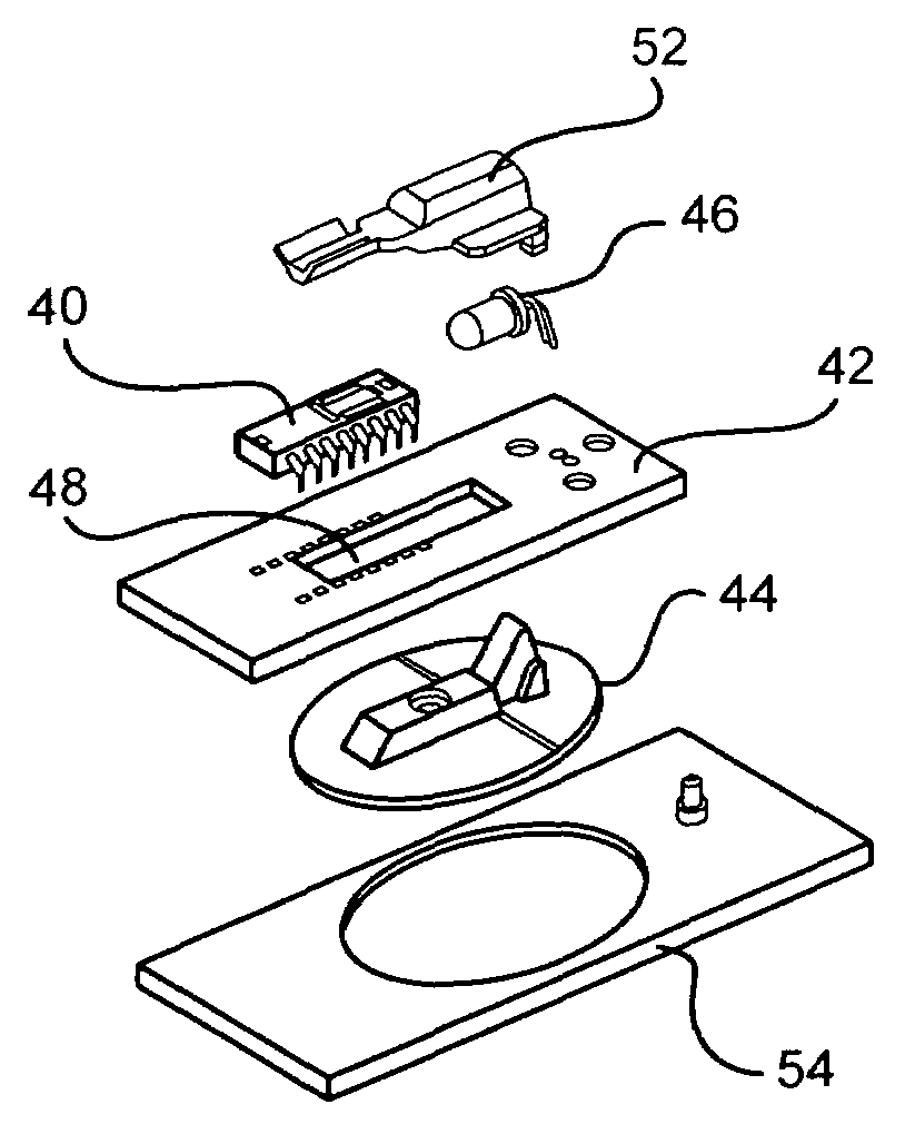
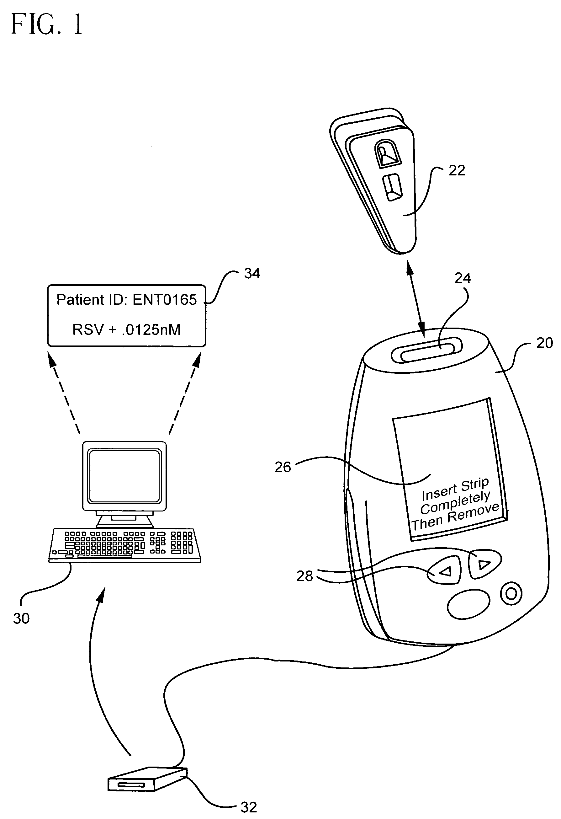
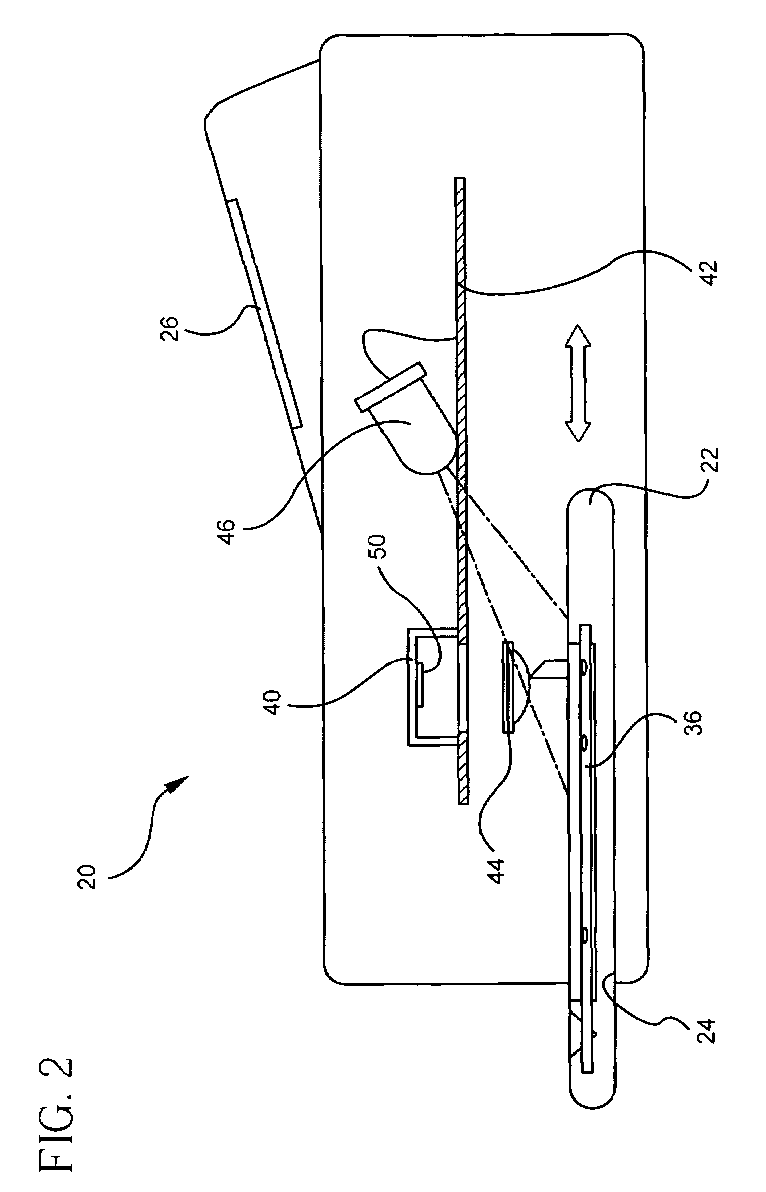
[0029]In accordance with the present invention, a reader having an optical mouse engine is provided for reading a test strip such as a Directigen lateral flow assay strip or other similar rapid manual test. The reader can also be used to collect data for other medical test data collection applications employing, for example, two-dimensional electrophoresis gels or multiple analyte, multi-stripe, lateral flow assays, among other data collection devices. As used herein, a test strip refers to any media on which patient test data or other data is generated, recorded, or displayed in a manner that forms an image or from which an image can be generated via the optical mouse engine. Such strips can include, but are not limited to, immunochromatographic test strips (e.g., lateral flow devices), x-ray films, radiographic assay films or images, films produced from sequencing gels, EKG printouts, MRI results, among others. Although referred to as a strip, media that can be read using an optic...


PUM

PropertyMeasurementUnit
timeaaaaaaaaaa
optical absorptionsaaaaaaaaaa
imaging arrayaaaaaaaaaa

Abstract

A test strip reader is provided with an optical mouse integrated circuit sensor that reads the test line, reference line and control line of a lateral flow assay strip by light absorption and determines the position of the test strip beneath the image on the integrated circuit board using digital signal processing algorithms. The digital signal processing algorithms process the imaged surface at a very high rate (e.g., 1500 frames per second) to determine the direction and speed of movement of the lateral strip with respect to the reader optics and image capture components. The sensor outputs this position information in a quadrature pattern format. A microcontroller uses the known position of the strip with respect to the reader to calculate the optical absorption of each colored reagent line, and the diagnostic significance (i.e., either qualitative or quantitative) of the test strip.

Description

FIELD OF THE INVENTION[0001]The invention relates to an apparatus and method for reading lateral flow assay strips or other two-dimensional data collection devices with an optical mouse engine. More particularly, the invention relates to an apparatus and method for using the optical mouse engine to determine the speed, direction and position of a strip as it is inserted into and withdrawn from a reader, as well as to provide a quantitative and / or qualitative assessment of the optically visible information on the strip.BACKGROUND OF THE INVENTION[0002]Lateral flow tests and lateral flow assays are becoming increasingly useful for clinical diagnostics, veterinary diagnostics, environmental screening, drug screening and food tasting, among other applications. Exemplary lateral flow tests include, but are not limited to, a pregnancy test (i.e., hCG), fertility and ovulation tests (i.e., LH and FSH), infectious disease tests (e.g., HIV, Strep A, H. Pylori, HbsAg, and Mononucleosis), PSA,...

Claims


Application Information

Patent Timeline
Patent Type & Authority Patents(United States)
IPC IPC(8): G06K9/00G01N33/543C12M1/34G01N21/86G06V30/144
CPCG01N21/8483G06K9/26G06V30/144
Inventor BACHUR, JR., NICHOLAS R.ARMSTRONG, ROBERT E.
Owner BECTON DICKINSON & CO
Why Eureka
Try Eureka