Method and apparatus for measuring and monitoring optical properties based on a ring-resonator

a technology of optical properties and ring resonance, applied in the direction of optics, optical elements, instruments, etc., can solve the problems of birefringence in optical components affecting quality, and achieve the effect of convenient relative frequency measuremen

Inactive Publication Date: 2008-11-04
PRESIDENT & FELLOWS OF HARVARD COLLEGE
View PDF15 Cites 24 Cited by
  • Summary
  • Abstract
  • Description
  • Claims
  • Application Information

AI Technical Summary

Benefits of technology

[0022]In still another embodiment of the invention the ring-resonator contains a reflecting surface in its optical path, and the gap distance is not changed, but the light is incident on the surface structure such that a surface plasmon resonance is excited by the light. For certain angles of incidence the surface-plasmon resonance (SPR) causes the reflectance to be at a minimum and simultaneously the phase of the p-polarized light undergoes a phase change different from the s-polarized light. It is known that the phase change of p-polarized (relative to s polarized) light as a function of the angle of incidence of the light can be a particularly sensitive means of observing SPR. The modes associated with the two polarization states (s and p polarized light) will have different resonance frequencies in the ring resonator and / or other performance characteristics. Monitoring the (relative) resonance frequencies and / or other performance characteristics and their possible change allows for frequency domain phase measurements of the surface plasmon resonance phenomenon and for a sensitive embodiment of a surface plasmon resonance sensor. Such a sensor can be used to detect biomolecules, bacteria viruses etc. binding to the metal surface since this binding is associated with a phase change of the SPR. In addition laterally scanning the surface makes is possible to obtain images of surfaces, possibly biological micro-array sensors, as a function of the relative change in resonance frequency between the modes that give rise to s and p polarized light. The embodiment has all the capabilities a standard surface plasmon resonance sensor has, but in addition it is able to measure and monitor the phase of the reflected light associated with the SPR phenomenon in real time and conveniently through relative frequency measurements.

Problems solved by technology

The residual birefringence in an optical component affects its quality, especially when used in polarization related instruments.

Method used


Image

  • Method and apparatus for measuring and monitoring optical properties based on a ring-resonator
  • Method and apparatus for measuring and monitoring optical properties based on a ring-resonator
  • Method and apparatus for measuring and monitoring optical properties based on a ring-resonator

Examples


example 1

[0094]Example 1 will be described with reference to FIGS. 5(a), 5(b), 6(a) and 6(b). A tunable distributed feedback (DFB) laser diode 510 operating at nominal infrared wavelength of 1.31 μm was coupled into a single mode optical fiber 530 using a single stage coupler (not shown). An inline optical isolator 520 isolates the source from the remaining optical circuit. Using a fiber optic U-bench (not shown) such as Thorlabs, part # FB220-FC, light is passed through a polarizer 610 and a half waveplate (λ / 2) 620. The optical fiber ring 560 is closed with a conventional 50 / 50 coupler 540, such as the Thorlabs, part # SMC11350229U. The light is detected using a conventional InGaAs photodetector 550, such as Thorlabs, part #PDA400. The laser wavelength may be tuned by modulation of the diode current at 100 Hz. For each scan, an intensity spectrum is measured with the photodiode 550 and digitally recorded on a computer (not shown). The tuning coefficient of the laser was previously determin...

example 2

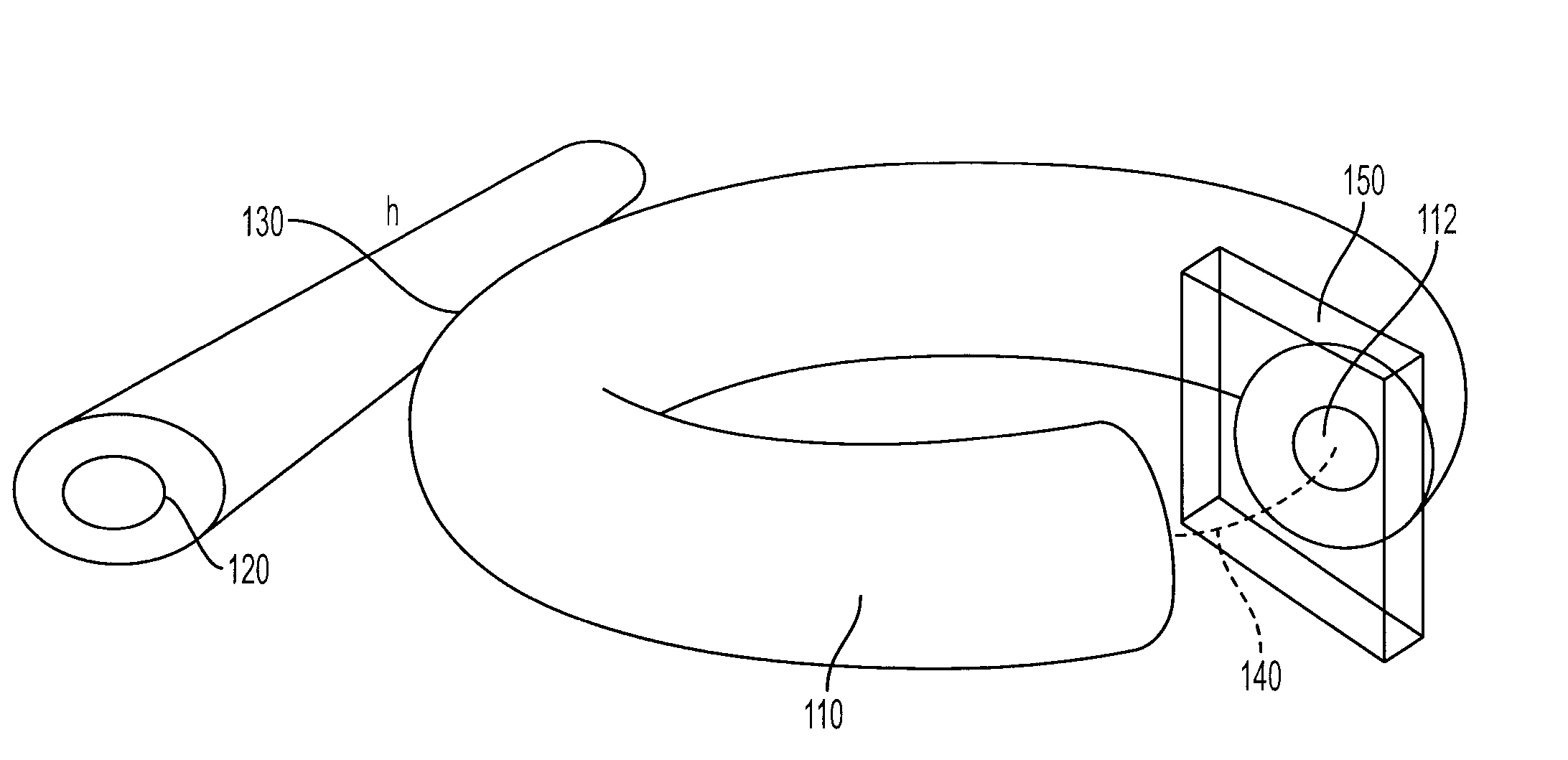
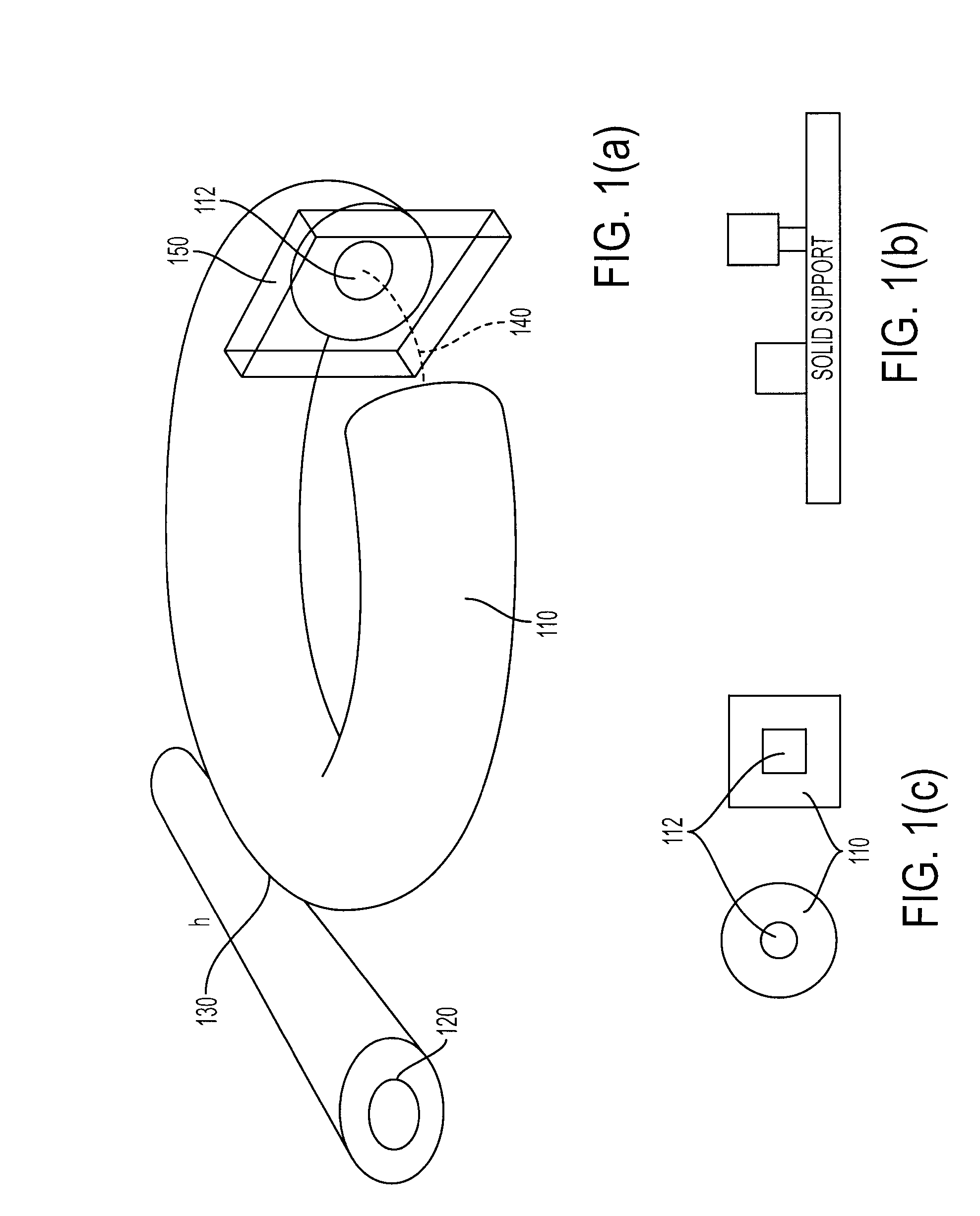
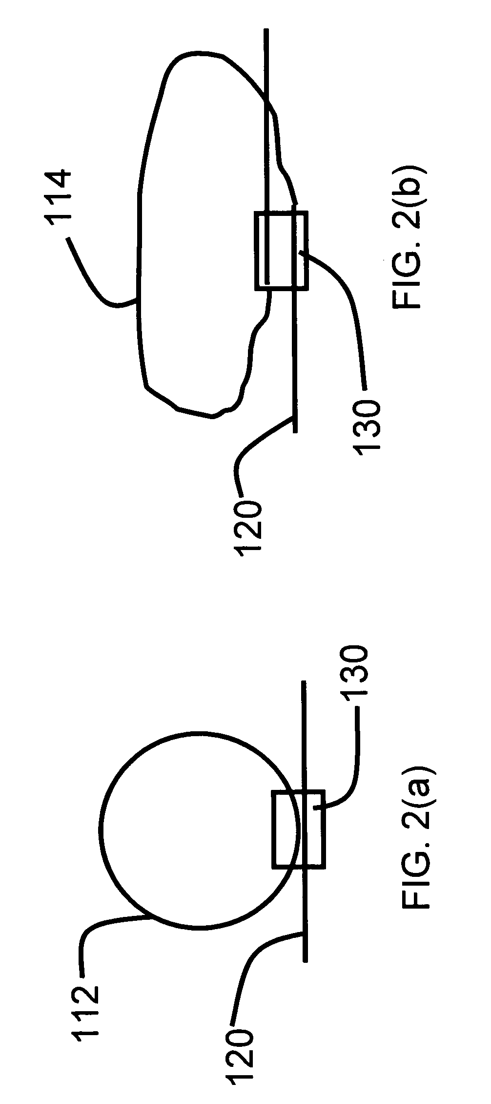
[0096]Example 2 will be described with reference to FIGS. 7(a) and (b). The figures schematically depict an alternate resonant ring structure for the measurement of refractive indices and or the detection of biological and / or chemical agents. It shows that the resonant light can be tapped using a second linear waveguide that is coupled to the resonator. This example directly demonstrates the presence of the two orthogonally polarized light states in the resonant ring. Two different polarization states are analyzed using the polarizer 720. It also shows how two or more resonant structures can be coupled using a common linear waveguide: instead of 720 and 750, the light can be rerouted to a different spectroscopic investigation e.g. another resonant structure. In the apparatus shown in FIG. 7(a), the optical circuit of FIG. 6(a) has an additional 50 / 50 coupler 740 and an additional polarizer 720. The second 50 / 50 coupler 740 allows resonant light to be coupled out of the ring. With th...

example 3

[0110]A sample cell of 10 cm path length was introduced into a resonant ring of ˜60 cm total circumference FIG. 10a. The sample cell was first filled with R-limonene. A transmission spectrum of the resonant modes was recorded using a tunable distributed feedback laser 510 with a nominal wavelength of 763 nm. The half-wave plate 620 was positioned so that two modes were excited simultaneously.

[0111]Before taking the measurements, the light is analyzed with the detector 950. A quarter waveplate 920 is positioned in the beam in front of a linear polarizer 910. By turning the polarizer by 90 degree we can select for one of the two orthogonal set of resonant modes (dark and light solid lines in FIG. 10b). By adjusting the quarter waveplate 930, the resonances were changed so that the two modes analyzed by 910 correspond to left and right circular polarized light respectively. The two modes with orthogonal polarization states can be observed as peaks by detector 950 or as dips by a photod...


PUM


Abstract

A method and apparatus for performing refractive index, birefringence and optical activity measurements of a material such as a solid, liquid, gas or thin film. The apparatus has an optical ring-resonator with a closed optical path that constitutes a cavity. A sample is introduced into the optical path of the resonator such that the light in the resonator is transmitted through the sample and relative and / or absolute shifts of the resonance frequencies or changes of the characteristics of the transmission spectrum are observed. A change in the transfer characteristics of the resonant ring, such as a shift of the resonance frequency, is related to a sample's refractive index (refractive indices) and / or change thereof. A reflecting surface may be introduced in a ring resonator. The reflecting surface can be raster-scanned for the purpose of height-profiling surface features.

Description

CROSS-REFERENCE TO RELATED APPLICATIONS[0001]The present application claims the benefit of the filing dates of U.S. Provisional Application Ser. No. 60 / 668,784 entitled “Method and Apparatus for Measuring Optical Properties,” and filed on Apr. 6, 2005 and U.S. Provisional Application Ser. No. 60 / 705,002 entitled “Method And Apparatus For Measuring And Monitoring Distances And Physical Properties As Well As Phase Changes Of Light Reflected From A Surface Based On A Ring-Resonator,” and filed on Aug. 3, 2005, both by inventors Frank Vollmer and Peer Fischer.[0002]The above cross-referenced related applications are hereby incorporated by reference herein in their entirety.STATEMENT REGARDING FEDERALLY SPONSORED RESEARCH OR DEVELOPMENT[0003]Not applicable.BACKGROUND OF THE INVENTION[0004]1. Field of the Invention[0005]The present invention relates to methods and devices for measuring optical properties such as refractive index, birefringence, and optical activity and for measuring and m...

Claims


Application Information

Patent Timeline
Patent Type & Authority Patents(United States)
IPC IPC(8): G01B9/02
CPCG01N21/23G01N21/39G01N21/45G01N21/553G01N21/7746G01N21/05G01N2021/432G01N2021/7789G02B2006/1213G01N2021/0346
Inventor VOLLMER, FRANKFISCHER, PEER
Owner PRESIDENT & FELLOWS OF HARVARD COLLEGE
Why Eureka
Try Eureka