
Material removal catheter and method

a technology of material removal and catheter, which is applied in the field of medical devices, systems and methods, can solve the problems of human blood vessels often becoming partly or fully occluded, serious injury or even death, and further complications

Inactive Publication Date: 2008-11-11
HAYASE MOTOYA +1
View PDF6 Cites 94 Cited by
  • Summary
  • Abstract
  • Description
  • Claims
  • Application Information

AI Technical Summary

Benefits of technology

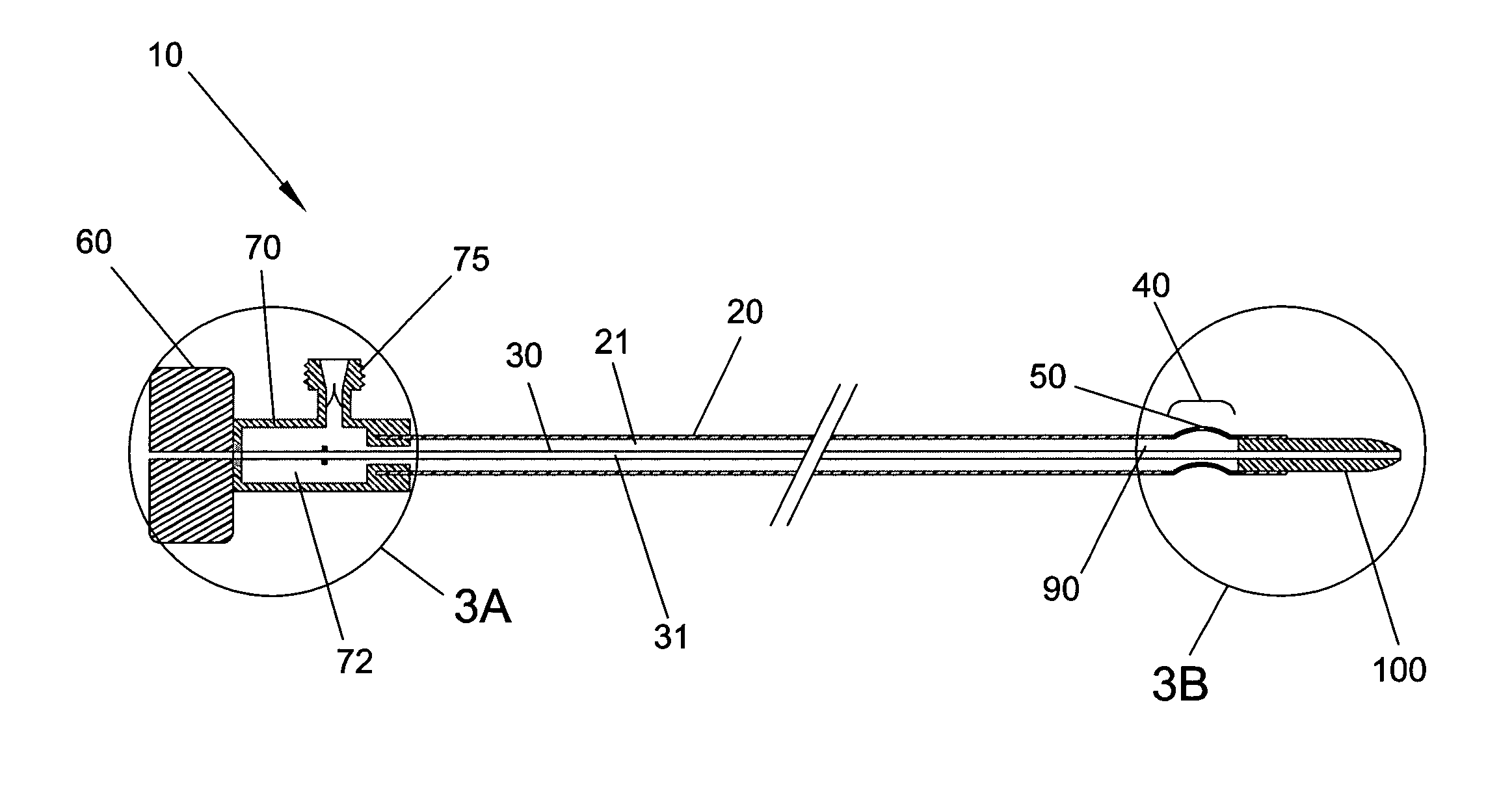
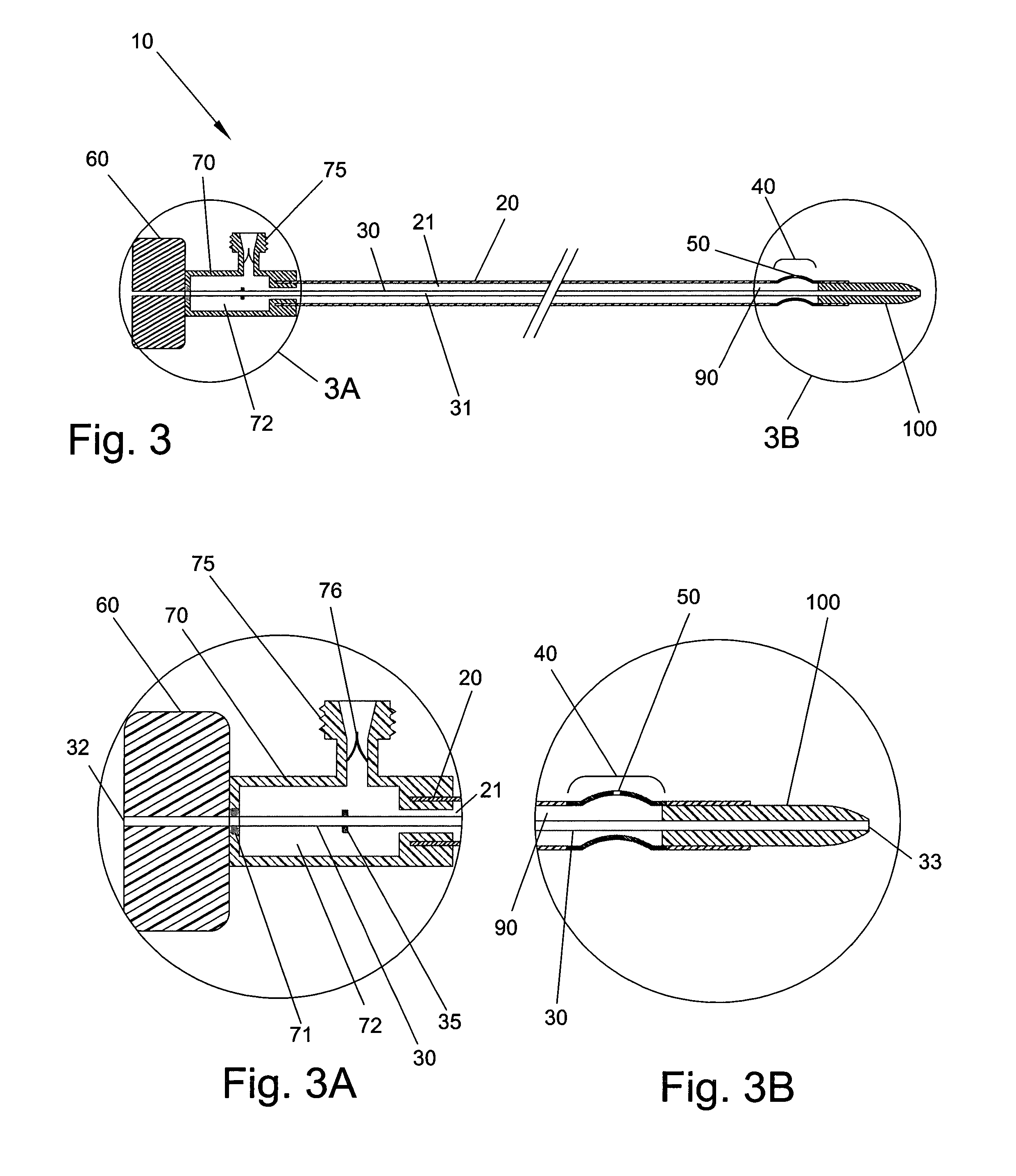
[0012]In a preferred embodiment, within a lumen of the catheter shaft is a sliding member that is connected to a mechanical linkage extending through the catheter shaft to the proximal portion of the device. The linkage is connected to sliding or other controls on the handle of the catheter device for advancement and retraction of the sliding member. In a preferred embodiment, the sliding member and mechanical linkage include a lumen permitting a guidewire to be placed through each. The linkage system may include one or more mechanical stops that limit the advancement or retraction. In the fully advanced position, the tip of the sliding member, which preferably is tapered, extends beyond the distal end of the catheter. The tip of the sliding member may extend beyond the end of the catheter in the fully retracted position as well. The sliding member can be used to change the geometry of the controllably arcuate segment. In a preferred embodiment, the controllably arcuate segment is normally bowed, and placing the sliding member within the lumen of the controllably arcuate segment changes the segment into a relatively straight geometry. To facilitate the change in shape of the controllably arcuate segment, the sliding member is constructed to be less flexible than the controllably arcuate segment. The sliding member, which may have a sharpened end that is oriented toward the opening, is advanced or retracted to move toward the opening thereby cutting and or pushing material away from the opening and into the material collection chamber. The one or more openings can have different cross sectional profiles, such as round or oval perimeters, or various angles of tapers, and may change geometry based on the geometry of the controllably arcuate segment and or the position of the sliding member. The material collection chamber may be located proximal or distal to the opening of the controllably arcuate segment, whereby the sliding member is retracted or advanced respectively to move the material received through the opening into the material collection chamber. In order to draw material from the outside of the catheter shaft through the opening in the controllably arcuate segment, a negative pressure or suction is applied at an opening on the proximal end of the catheter device. Aspiration or negative pressure may be maintained during the period of time that the sliding member is advanced or retracted. The present invention includes various means of providing the suction including connections to attach to syringes or sophisticated vacuum and material collection generators as well as integrated aspiration systems. The present invention may include one or more valves to prevent blood leakage, avoid over pressurization, allow one way flow of fluid and other material into or out of various chambers or other locations and other purposes.
[0019]The present invention, therefore, provides a catheter device for removing undesirable material, such as thrombus, from a body conduit, such as a saphenous vein graft or other blood vessel, including a controllably arcuate segment which further includes an opening that can be brought in contact with the undesired material with sufficient force such than under suction, the material is drawn through the opening into an lumen, cavity or chamber within the catheter device. The use of the device is simple and straightforward, and does not require bulky or expensive equipment not otherwise included in the various hospital settings in which it will be used.

Problems solved by technology

Human blood vessels often become partly or fully occluded by various undesired materials including plaque, thrombi or other substances that restrict the flow of blood within the vessel.
Depending on the location of the occlusion, serious injury or even death can occur.
Coronary heart disease is an extremely common form of this occlusive disease, and is the leading cause of death in the United States.
All of these therapeutic options involve the risk of dislodging a portion of the occlusive material, causing embolus to move downstream thus causing further complications.
Heart bypass surgery is an extremely invasive and traumatic form of therapy to treat coronary occlusive disease.
These saphenous vein grafts often used in heart bypass procedures are also susceptible to occlusive disease, and over time may become restricted by plaque and thrombus.
Atherosclerotic plaque in saphenous vein grafts tends to be softer and more friable than their arterial counterparts and thus more prone to embolizing during treatment.
Chemical thrombolytic drugs are available to treat saphenous vein grafts but require the patient to be non-ambulatory throughout their use and have numerous risks and complications.
Balloon angioplasty of saphenous vein grafts is associated with a higher rate of embolus generation, potentially migrating downstream to block a portion of the coronary artery to which it is attached and causing a myocardial infarction.
These devices are expensive, and complicated to use.
Vacuum extraction catheters have been developed to treat saphenous vein grafts, however they tend to be large and bulky and have had sub optimal results and numerous complications.

Method used


Image

  • Material removal catheter and method
  • Material removal catheter and method
  • Material removal catheter and method

Examples


Embodiment Construction

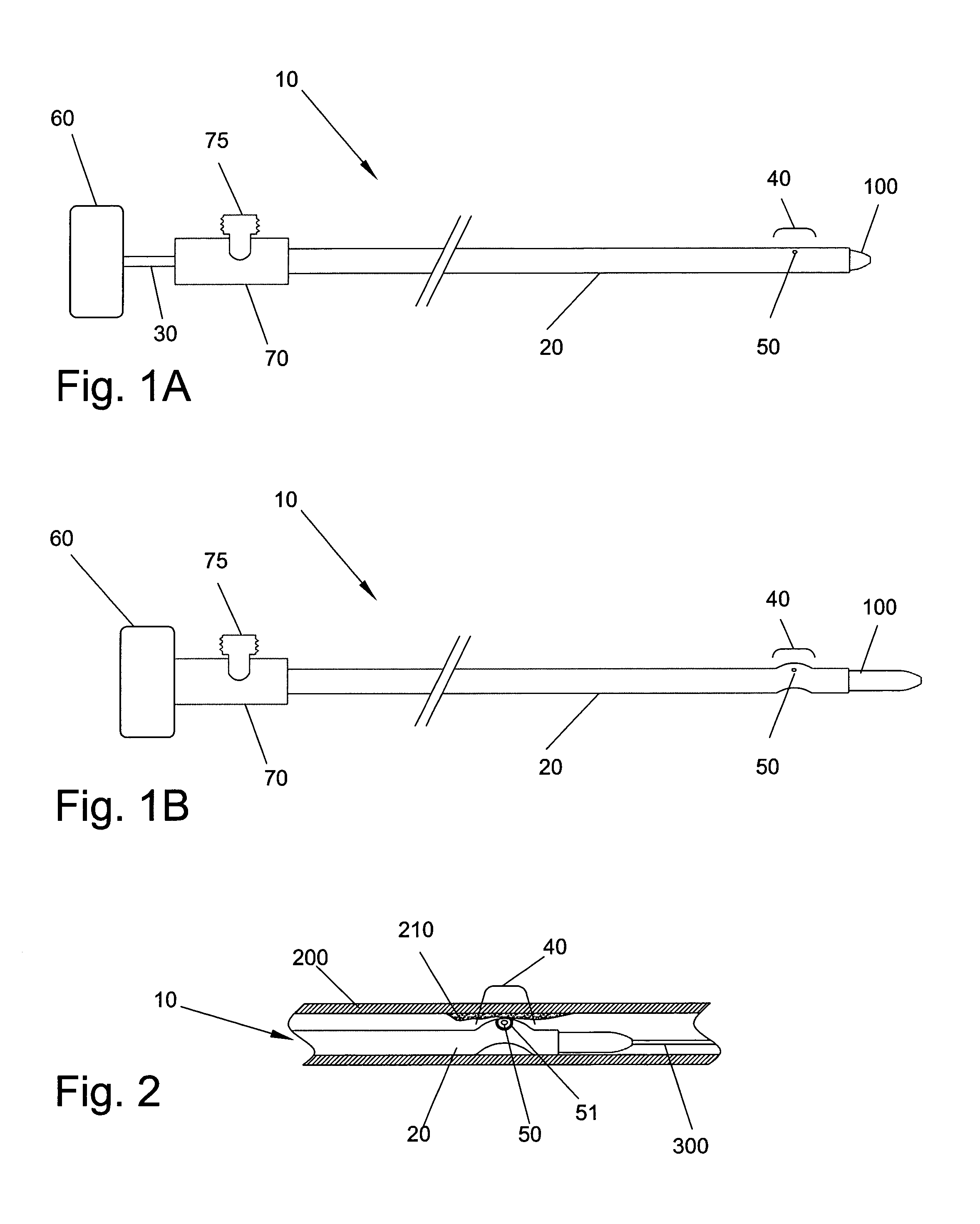
[0046]Referring first to FIGS. 1A and 1B, there is illustrated an exemplary embodiment of a catheter device 10 constructed in accordance with the present invention. The catheter device 10 includes a catheter shaft 20 constructed of materials that are biocompatible and also permit flexibility of the device required to allow insertion into and advancement through the vasculature of a patient. Catheter shaft 20 contains one or more hollow lumens within its structure that allow flow of material such as blood or thrombus, as well as permit controlling shafts, mechanical linkages or flexible tubes or wires to slide back and forth. Fixedly attached to the proximal end of catheter shaft 20 is a handle, handle 70, which allows the user to advance and maintain the position of the distal end of catheter device 10, as well as rotate the catheter shaft 20.

[0047]Handle 20 includes aspiration port 75 that is in fluid communication with an internal lumen of catheter shaft 20. Aspiration port 75 can...


PUM


Abstract

A catheter device that is useable to extract material from a body conduit, such as a blood vessel, comprises a flexible catheter advanceable into the body conduit, an opening in the wall of the catheter that is in fluid communication with a material collection chamber, and a controllably arcuate segment along the catheter shaft, near the distal tip of the catheter and including the opening. Further said catheter may include a sliding member, located within a lumen of the catheter, that is used to move the material entering the catheter through the arcuate segment opening, into the material collection chamber and away from said opening. The catheter may include a single mechanism utilized to both generate a vacuum to cause material to enter the catheter at the arcuate segment opening and also cause the sliding member to travel, inside the catheter, moving material away from the opening and into the material collection chamber. Methods of utilizing such a catheter device to remove material from a body conduit are also disclosed.

Description

FIELD OF THE INVENTION[0001]The present invention relates generally to medical devices, systems and methods and more particularly to a material removal catheter and methods that are useable to remove thrombus and other undesired material from the vasculature or other internal conduit of a patient, the apparatus being particularly well suited for saphenous vein grafts, coronary arteries and the peripheral vasculature.BACKGROUND OF THE INVENTION[0002]Human blood vessels often become partly or fully occluded by various undesired materials including plaque, thrombi or other substances that restrict the flow of blood within the vessel. Depending on the location of the occlusion, serious injury or even death can occur. When diagnosed, it is often advantageous to remove the occlusive material in a safe and effective manner. Coronary heart disease is an extremely common form of this occlusive disease, and is the leading cause of death in the United States.[0003]Arteriosclerosis is a chronic...

Claims


Application Information

Patent Timeline
Patent Type & Authority Patents(United States)
IPC IPC(8): A61M31/00
CPCA61M25/0054A61M25/0069A61M2025/0063A61B17/22A61B2017/22079A61M25/0108A61M25/0155
Inventor HAYASE, MOTOYAFLAHERTY, J. CHRISTOPHER
Owner HAYASE MOTOYA
Learn More