

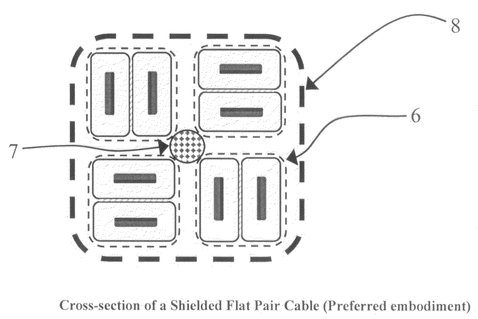
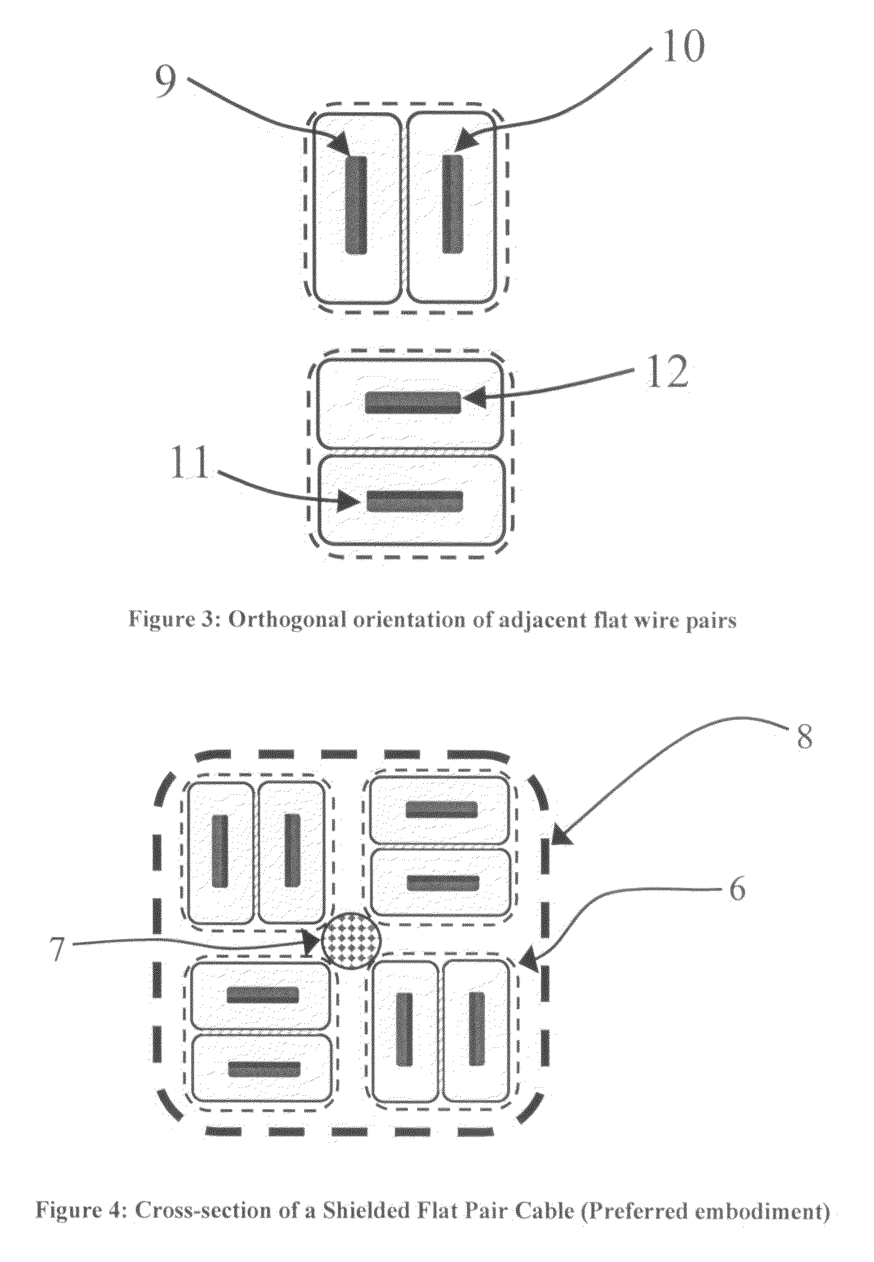
Shielded flat pair cable architecture
a flat pair cable and shielding technology, applied in the field of shielded flat pair cable architecture, can solve the problems of insufficient but non-ideal connectivity between different parts of the system, energy loss, data rate, etc., and achieve the effects of reducing signal loss, reducing crosstalk, and eliminating intra-pair skew
- Summary
- Abstract
- Description
- Claims
- Application Information
AI Technical Summary
Benefits of technology
Problems solved by technology
Method used
Image

Examples
Embodiment Construction
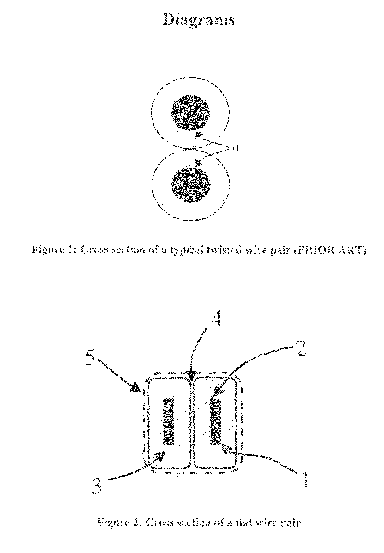
[0017]A prior art twisted wire pair (TWP) cross-section is illustrated in FIG. 1. Key aspects of the design of such a transmission line pair include a fixed separation between the central axes of the two conducting wires, the diameter of the wires and the thickness as well as dielectric permittivity of the insulation coating both wires. The electric field between the two wires passes through the insulation between the wires as well as air space adjacent to them, given the circular nature of the cross section of the wires. The dimensions of the wires, their separation and the nature of the insulating material in between provide a value of inductance and capacitance per unit length that determine the characteristic impedance of the transmission line as the square-root of the ratio of the inductance to the capacitance. Prior art US patents [7] and [8] teach of techniques to be employed such that the individual wires are maintained at the same relative position with respect to each othe...
PUM
| Property | Measurement | Unit |
|---|---|---|
| length | aaaaa | aaaaa |
| conductive | aaaaa | aaaaa |
| relative dielectric permittivity | aaaaa | aaaaa |
Abstract
Description
Claims
Application Information