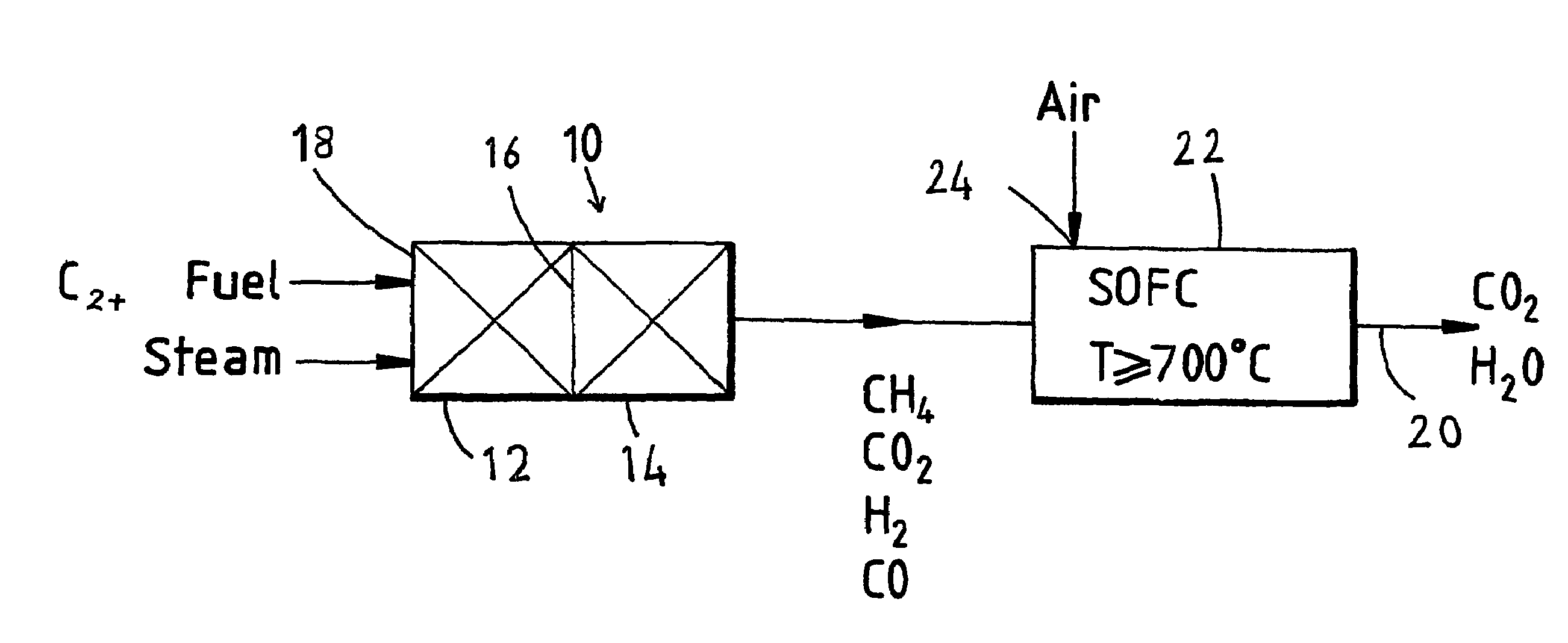
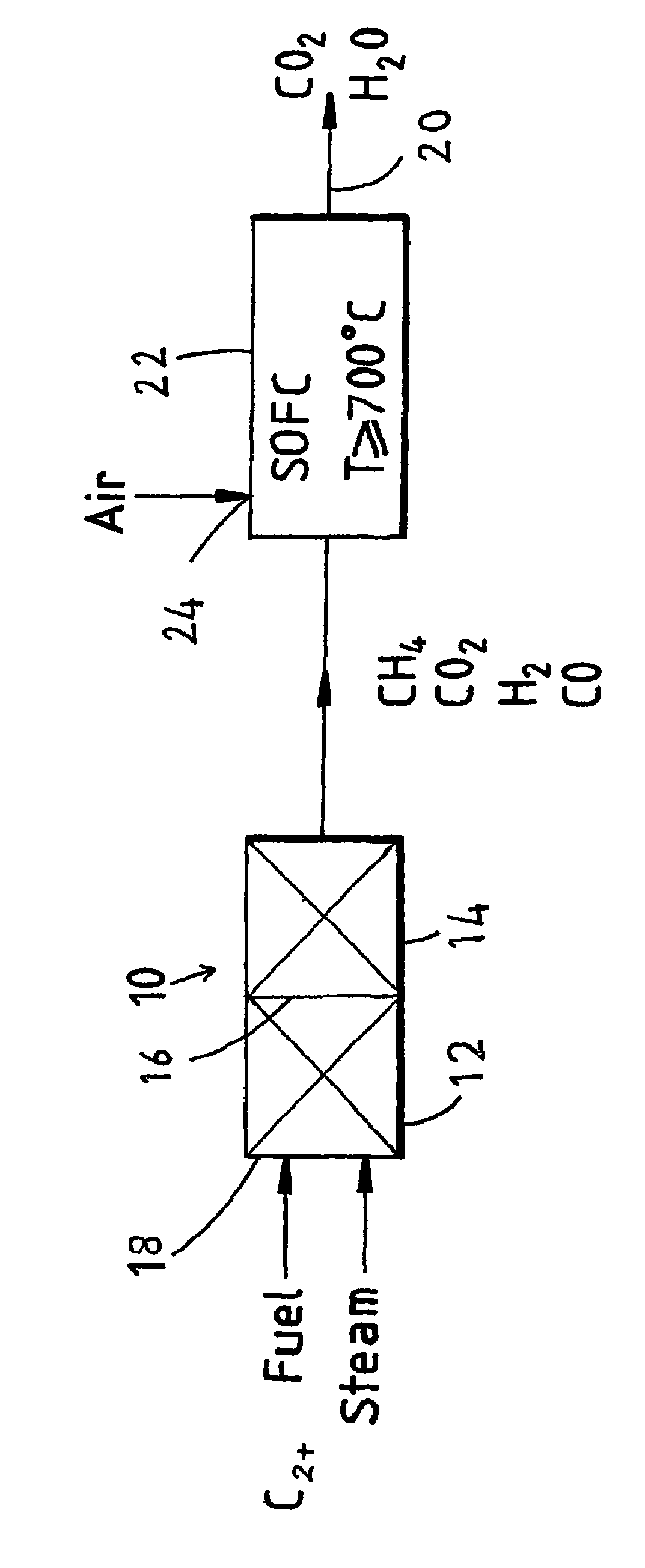
Fuel cell system
a fuel cell and system technology, applied in the field of fuel cells, can solve problems such as thermodynamic and/or kinetic, and achieve the effects of improving thermal conductivity across the stack, reducing excessive cooling, and simple construction
- Summary
- Abstract
- Description
- Claims
- Application Information
AI Technical Summary
Benefits of technology
Problems solved by technology
Method used
Image
Examples
example 1
[0057]Case 1: A single-stage reformer operated at 400° C.[0058]Case 2: A two-stage reformer with the first stage operated at 450° C. and the second stage at 350° C.
[0059]A pure propane feed with a steam-to-carbon ratio of 1.5 is used in these calculations.
[0060]The results are as follows:
[0061]
Case 1:Methane:56.45%(v / v)Hydrogen:24.71Carbon Dioxide:18.34Carbon Monoxide:0.50Case 2Methane:66.48%(v / v)Hydrogen:15.52Carbon Dioxide:17.86Carbon Monoxide:0.14
[0062]It may be seen that the resultant fuel stream methane content is higher in Case 2. In principle the methane content for Case 1 can be increased by operating at the lower temperature of 350° C. However, in practice most commercial catalysts will not have sufficiently high activity for full conversion of higher hydrocarbons at such low temperatures. Similarly, the temperature of the second stage of Case 2 can be lowered to 300° C. for higher methane content. Again, similar practical restrictions apply. From these considerations the a...
example 2
[0063]Case 1: A single-stage reformer operated at 380° C.[0064]Case 2: A two-stage reformer with the first stage operated at 380° C. and the second stage at 334° C.
[0065]A pure propane feed with a steam-to-carbon ratio of 1.5 is used in these calculations.
[0066]The results are as follows:
[0067]
Case 1:Methane:61.84%(v / v)Hydrogen:22.45Carbon Dioxide:15.43Carbon Monoxide:0.28Case 2:Methane:71.4%(v / v)Hydrogen:14.1Carbon Dioxide:14.4Carbon Monoxide:0.1
example 3
[0068]Example 2 was experimented in a dual-bed microreactor. In the first experiment, the first bed was loaded with 1 g of the catalyst C11-PR, a commercial pre-reforming catalyst obtained from United Catalysts Inc. The experiment was performed with the first bed maintained at 380° C. and with no catalyst placed in the second bed. The experiment was therefore a comparative example in accordance with Case 1 of Example 2 and with the process of PCT / AU00 / 00974. The experiment was performed over a period of 100 hours. Steam-to-Carbon ratio was 1.5 and the space velocity of the reactant was 1250 h−1. The results are as follows:
[0069]
TABLE 1Propane pre-reforming in a single-bed microreactorHours OnGas CompositionSelectivityStreamC3H8CO2H2CH4CH4 / H2 2.2013.625.860.52.35 4.8013.725.360.82.4 7.3013.626.260.02.2925.3013.923.8261.62.5927.8013.924.861.22.4730.3013.825.360.72.496.8013.825.560.52.3799.3013.726.259.92.29101.8 013.726.359.82.28102.8 013.726.559.72.25Average013.725.660.52.37
PUM
| Property | Measurement | Unit |
|---|---|---|
| temperature | aaaaa | aaaaa |
| temperature | aaaaa | aaaaa |
| temperature | aaaaa | aaaaa |
Abstract
Description
Claims
Application Information
 - R&D
- Intellectual Property
- Life Sciences
- Materials
- Tech Scout
- Unparalleled Data Quality
- Higher Quality Content
- 60% Fewer Hallucinations
Browse by: Latest US Patents, China's latest patents, Technical Efficacy Thesaurus, Application Domain, Technology Topic, Popular Technical Reports.
© 2025 PatSnap. All rights reserved.Legal|Privacy policy|Modern Slavery Act Transparency Statement|Sitemap|About US| Contact US: help@patsnap.com


