Efficient gas-separation process to upgrade dilute methane stream for use as fuel

a technology of gas separation and methane, which is applied in the direction of separation process, liquefaction, lighting and heating apparatus, etc., can solve the problems of reducing the gwp of emissions and not providing any energy recovery

Active Publication Date: 2009-11-12
MEMBRANE TECH & RES
View PDF16 Cites 6 Cited by
  • Summary
  • Abstract
  • Description
  • Claims
  • Application Information

AI Technical Summary

Benefits of technology

[0027]By using sweep-mode operation and by using air or other oxygen-containing gas as the sweep gas, the membrane separation step is carried out in a very energy efficient

Problems solved by technology

This option does not provide any energy recovery, but

Method used


Image

  • Efficient gas-separation process to upgrade dilute methane stream for use as fuel
  • Efficient gas-separation process to upgrade dilute methane stream for use as fuel
  • Efficient gas-separation process to upgrade dilute methane stream for use as fuel

Examples


example 1

Bases of Calculations for Other Examples

[0104](a) Membrane permeation experiments:[0105](i) A set of permeation experiments was performed with a composite membrane having a polyether-based selective layer. The pure gas permeation properties of the membrane as measured at 100 psia and 30° C. are shown in Table 1.

TABLE 2GasPermeance (gpu)*CO2 / Gas SelectivityCarbon dioxide1,000—Nitrogen2050Oxygen5020Methane5020Water**>2,000*Gas permeation unit; 1 gpu = 1 × 10⁻⁶ cm3(STP) / cm2 · s · cmHg**Estimated, not measured[0106](ii) A set of permeation experiments was performed with a composite membrane having a fluorinated selective layer, of the type described in detail in U.S. Pat. Nos. 6,361,582 and 6,361,583. The pure gas permeation properties of the membrane as measured at 100 psia and 30C are shown in Table 3.

TABLE 3GasPermeance (gpu)CO2 / Gas SelectivityCarbon dioxide160—Nitrogen325Oxygen1001.6Methane1610

[0107](b) Calculation methodology: All calculations were performed with a modeling program...

example 2

Process of the Invention

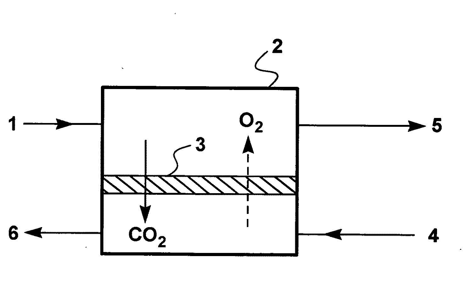
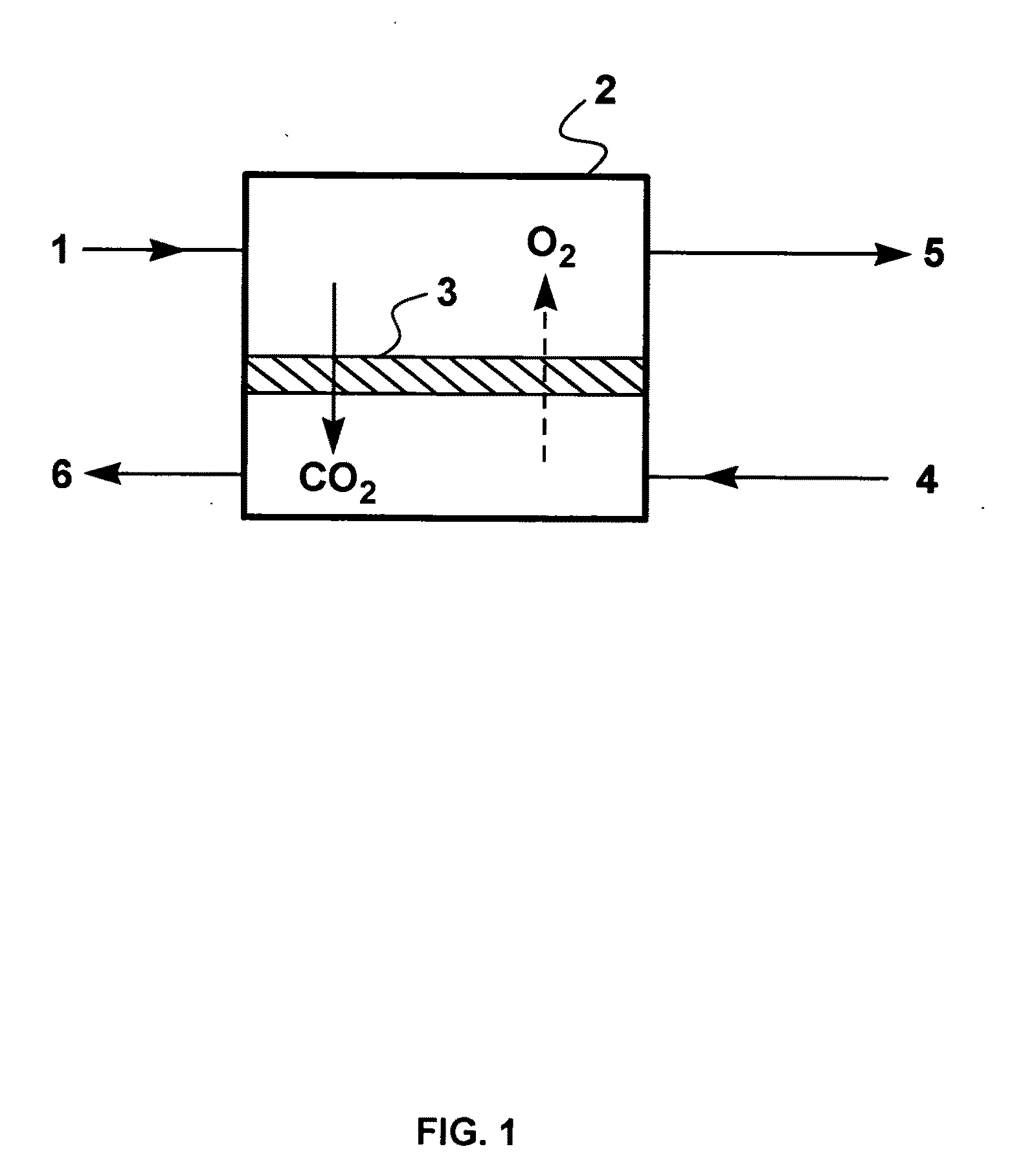
[0108]A calculation was performed to illustrate the treatment of a raw methane-containing gas stream according to the process of FIG. 1. The feed gas (stream 1) was assumed to contain 20% methane and 80% carbon dioxide; this composition is typical of a landfill gas stream at a later stage of operation, or of an off-gas from an amine absorption natural gas processing plant. The calculations also assumed that the feed gas to the membrane separation step was at 50 psig, again a typical representative number for landfill gas or various process off-gases.

[0109]Air at atmospheric pressure (stream 4) was assumed to be circulated on the other side of the membrane using a blower.

[0110]The assumptions for the membrane performance were as in Example 1(a)(ii).

[0111]The results of the calculation are shown in Table 4.

TABLE 4Stream1546ParameterFeedResidueSweepPermeate / SweepFlow rate (MMscfd)10.322.7Pressure (psig)505000Component (vol %)Methane2053.6—1.4Carbon Dioxide8032.8...

example 3

Not in Accordance with the Invention

[0117]A calculation was performed to illustrate a conventional two-stage process for treating raw natural gas containing 10 vol % according to the process flow scheme of FIG. 4.

[0118]It was assumed that the feed gas (stream 41) is available at 1,00 psia (985 psig) and that a pressure of 100 psia (85 psig) is maintained on the permeate side of first membrane separation unit, 43. It was further assumed that the first permeate stream (46) is recompressed to 1,00 psia, and that the permeate pressure for the second membrane separation unit is maintained at 50 psia (35 psig).

[0119]The assumptions for the membrane performance were as in Example 1(a)(ii).

[0120]The results of the calculation are shown in Table 5.

TABLE 5Stream46524145FirstSecondParameterFeedResiduepermeatepermeateFlow rate (MMscfd)2.28.83.41.2Pressure (psig)9859858535Component (vol %)Methane90987030Carbon Dioxide1023070Oxygen————Nitrogen————

[0121]The horsepower requirement to operate compr...


PUM


Abstract

A membrane-based gas separation process for treating gas streams that contain methane in low concentrations. The invention involves flowing the stream to be treated across the feed side of a membrane and flowing a sweep gas stream, usually air, across the permeate side. Carbon dioxide permeates the membrane preferentially and is picked up in the sweep air stream on the permeate side; oxygen permeates in the other direction and is picked up in the methane-containing stream. The resulting residue stream is enriched in methane as well as oxygen and has an EMC value enabling it to be either flared or combusted by mixing with ordinary air.

Description

[0001]This application claims the benefit of U.S. Provisional Application Ser. No. 61 / 127,415, filed May 12, 2008 and incorporated herein by reference.[0002]This invention was made in part with Government support under award numbers DE-FG02-06ER84609 and DE-FG02-07ER84819, awarded by the United States Department of Energy. The Government has certain rights in this invention.FIELD OF THE INVENTION[0003]The invention relates to gas separation membranes, and specifically to processes using a sweep gas on the permeate side of the membranes to upgrade streams containing methane in low concentrations for use as fuel.BACKGROUND OF THE INVENTION[0004]Methane is a valuable energy resource, but, after carbon dioxide, is the largest contributor to global warming. Methane accounts for about 10% of U.S. greenhouse gas emissions, and has almost eight times the global warming effect of an equivalent volume of carbon dioxide (21 times on a mass basis). Most emissions take the form of dilute mixture...

Claims


Application Information

Patent Timeline
IPC IPC(8): B01D53/22B01D53/54B01D53/62
CPCB01D53/22B01D2256/22B01D2257/504Y10S585/903Y02C10/10Y02E50/346Y02C10/04Y02C20/40Y02E50/30
Inventor WIJMANS, JOHANNES G.MERKEL, TIMOTHY C.LIN, HAIQINGTHOMPSON, SCOTTDANIELS, RAMIN
Owner MEMBRANE TECH & RES
Why Eureka
Try Eureka