Method for treating a flow of gas and gas treatment system

a gas treatment system and flow technology, applied in the direction of combustible gas purification/modification, process and machine control, nuclear elements, etc., can solve the problems of undesirable corrosion phenomena of components, and achieve the effect of simple and rapid process operation

Inactive Publication Date: 2008-11-25
AREVA GMBH
View PDF16 Cites 1 Cited by
  • Summary
  • Abstract
  • Description
  • Claims
  • Application Information

AI Technical Summary

Benefits of technology

[0006]In the operation of a nuclear plant, in particular a nuclear power station, a customary design objective is the best possible avoidance of corrosion damage on important components, especially in the primary region of the respective plant, for example on graphite internals, fuel assemblies or other components in the pressure vessel of the reactor. This is because substantial avoidance of corrosion damage on these components should increase the life or operating time and keep down the maintenance and repair requirement associated with the alleviation of corrosion damage in the primary region of the nuclear plant, which is sometimes considerable. For this reason, the use of helium may be specified as a working or cooling medium in a nuclear plant, in particular in the primary circuit of a high-temperature reactor. This is because helium is chemically inert, so that, for example, corrosion phenomena caused by the cooling gas on the components specified does not have to be reckoned with when helium is used as the cooling gas for these components.
[0033]The normal operation of a catalytic adsorber module and the regeneration of a catalytic adsorber module are thus effected at the same time and thus in one process operation. Even after “consumption” of the oxygen-carrying component has occurred in the first, upstream catalytic adsorber module, the gas treatment system can be utilized further without an appreciable interruption to operation after the positions of the catalytic adsorber modules in the flow path of the gas stream have simply been switched over so that the previously regenerated adsorber module is now used as first, upstream catalytic adsorber module for the oxidation of impurities in the gas stream and the “exhausted” catalytic adsorber module is now regenerated at the same time. As a result of the continuous operation of the gas treatment system, in which interruptions to operation for specific regeneration of individual adsorber modules are no longer necessary, made possible in this way, redundancies or multi-stream configurations of such systems can be dispensed with or at least reduced. In addition, the integration of the active components into a common pressurized enclosure achieves a particularly compact and thus space-saving construction in which particularly simple and rapid process operation is additionally made possible as a result of the decoupling of maintenance of the pressure from the thermally stressed structural components.

Problems solved by technology

The impurities can in turn lead to undesirable corrosion phenomena on the components specified.

Method used


Image

  • Method for treating a flow of gas and gas treatment system
  • Method for treating a flow of gas and gas treatment system
  • Method for treating a flow of gas and gas treatment system

Examples


Embodiment Construction

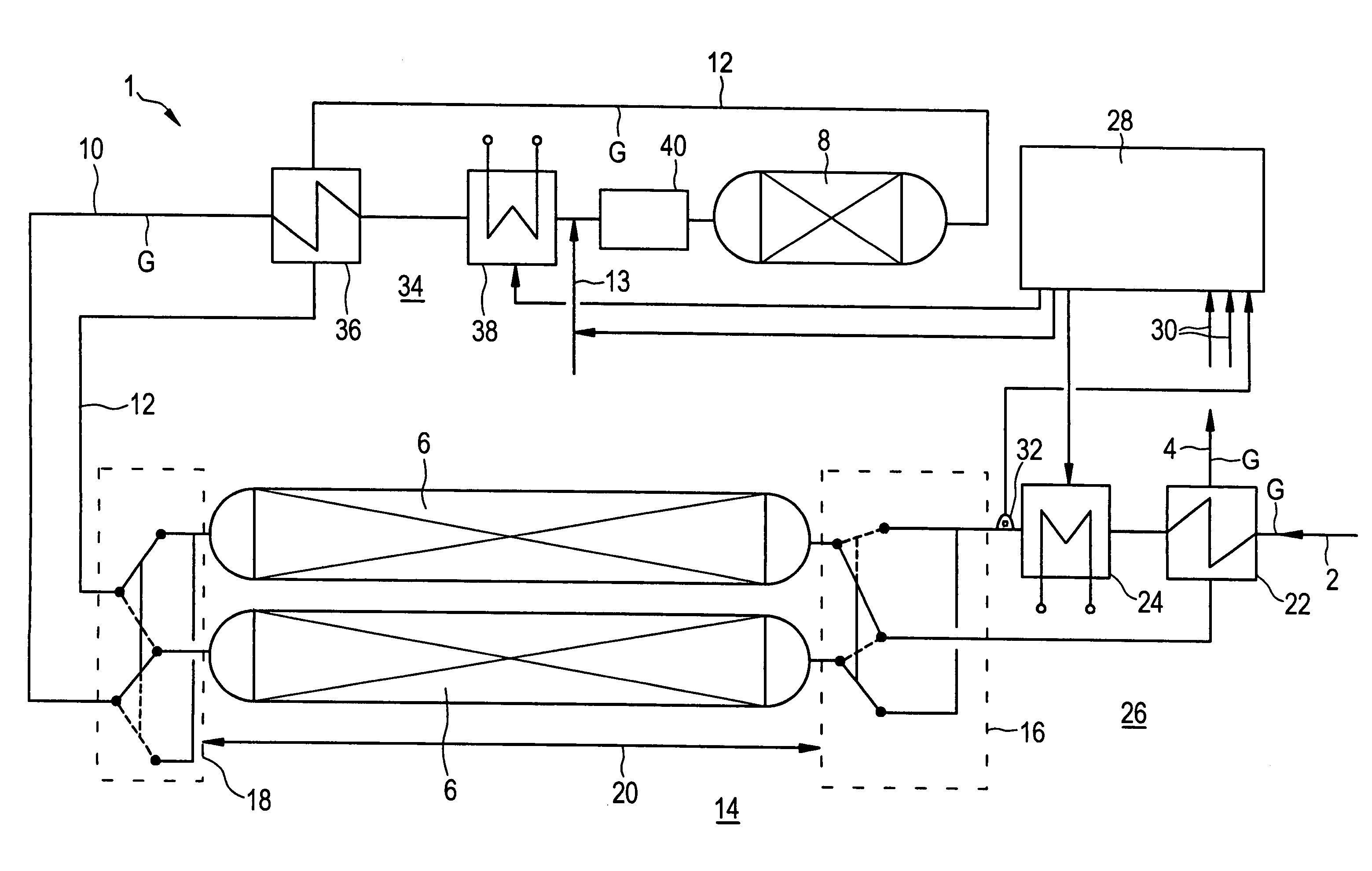
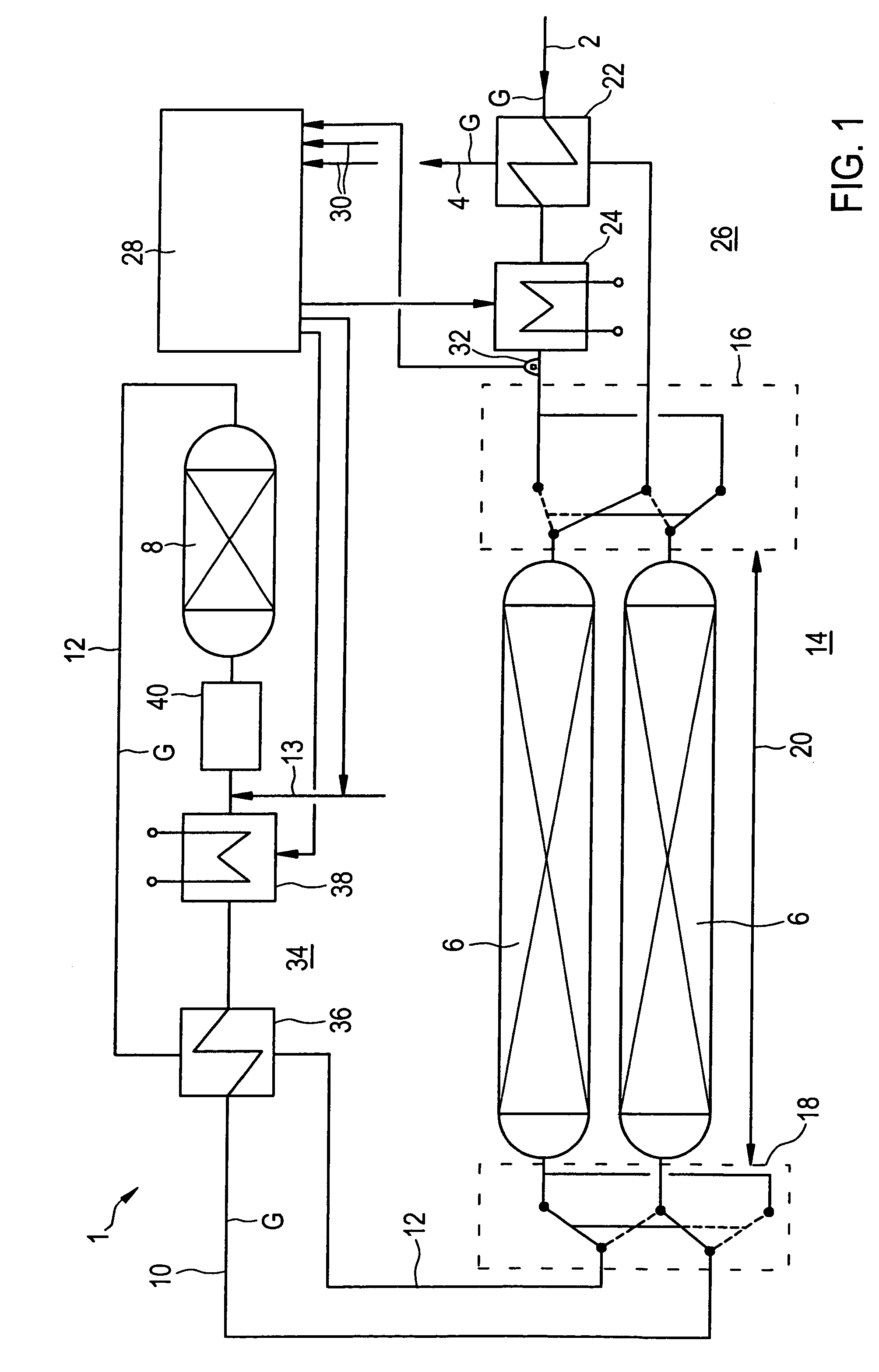
[0040]In all the figures of the drawing, sub-features and integral parts that correspond to one another bear the same reference symbol in each case. Referring now to the figures of the drawing in detail and first, particularly, to FIG. 1 thereof, there is shown a gas treatment system 1. The gas treatment system 1 is provided for the treatment of a gas stream G, namely a substream from a helium primary cooling circuit of a nuclear plant, which is not shown in more detail. For this purpose, the gas treatment system 1 is connected via a gas feed line 2 and a gas discharge line 4 to the helium primary cooling circuit, which is not shown in more detail, of the nuclear plant.

[0041]The gas treatment system 1 is provided for the targeted removal of impurities, for example hydrogen, carbon monoxide, methane or tritium, which are possibly entrained in the helium of the gas stream G. The removal of hydrogen and carbon monoxide is to be effected by oxidation to water and carbon dioxide, respect...


PUM

PropertyMeasurementUnit
temperatureaaaaaaaaaa
operating temperatureaaaaaaaaaa

Abstract

A method treats a flow gas that is guided via a catalytic adsorber module to oxidize contaminants carried in the flow gas. The method reliably purifies the flow gas using equipment that is held to a comparatively low level of complexity. To this end, the flow gas is guided in a first purification step via a first catalytic adsorber module to oxidize contaminants carried along therewith, during which molecular or atomic oxygen is added to the flow gas, and the flow gas mixed with the added oxygen is guided in a second purification step via an oxidation catalyst. The flow gas flowing away from the oxidation catalyst is guided in a third purification step via a second catalytic adsorber module to reduce excessive oxygen.

Description

CROSS-REFERENCE TO RELATED APPLICATION[0001]This is a continuing application, under 35 U.S.C. § 120, of copending international application No. PCT / EP2003 / 010103, filed Sep. 11, 2003, which designated the United States; this application also claims the priority, under 35 U.S.C. § 119, of German patent application No. 102 46 252.6, filed Oct. 2, 2002; the prior applications are herewith incorporated by reference in their entirety.BACKGROUND OF THE INVENTION[0002]1. Field of the Invention[0003]The invention relates to a process for the treatment of a gas stream, in which the gas stream is passed over a catalytic adsorber module to oxidize entrained impurities. It further relates to a gas treatment system suitable for carrying out the process.[0004]2. Summary of the Invention[0005]It is accordingly an object of the invention to provide a method for treating a flow of gas and a gas treatment system that overcome the above-mentioned disadvantages of the prior art devices and methods of t...

Claims


Application Information

Patent Timeline
Patent Type & Authority Patents(United States)
IPC IPC(8): B01D53/02B01D53/34B01J12/00B01J19/00G21C15/00G21C3/56B01D53/86
CPCB01D53/02B01D53/0415B01D53/8668B01D2253/10B01D2253/112B01D2255/20761B01D2256/18B01D2257/104B01D2259/40001B01D2259/40086B01D2259/402
Inventor HILL, AXEL
Owner AREVA GMBH
Why Eureka
Try Eureka