Optical module and method for monitoring and controlling wavelengths

a wavelength monitoring and controlling technology, applied in the direction of optical radiation measurement, instruments, semiconductor lasers, etc., can solve the problems of difficult to reduce production costs, difficult to make the wavelength monitoring and controlling system small in size, and high cost of optical systems, so as to reduce power consumption and improve reliability in operation management, the effect of reducing the operation cos

Inactive Publication Date: 2008-12-02
NIPPON TELEGRAPH & TELEPHONE CORP
View PDF17 Cites 9 Cited by
  • Summary
  • Abstract
  • Description
  • Claims
  • Application Information

AI Technical Summary

Benefits of technology

[0012]The present invention was developed in order to solve such problems and shortcomings. It is therefore an object of the invention to provide an optical module and its wavelength monitoring and controlling method, enabling small size and low power consumption without requiring any complicated optical system in its wavelength monitoring and controlling mechanism. Further, it is another object of the invention to provide an optical module and its wavelength monitoring and controlling method which is capable of controlling a wavelength of light emitted from a laser diode (LD) to a desired value.
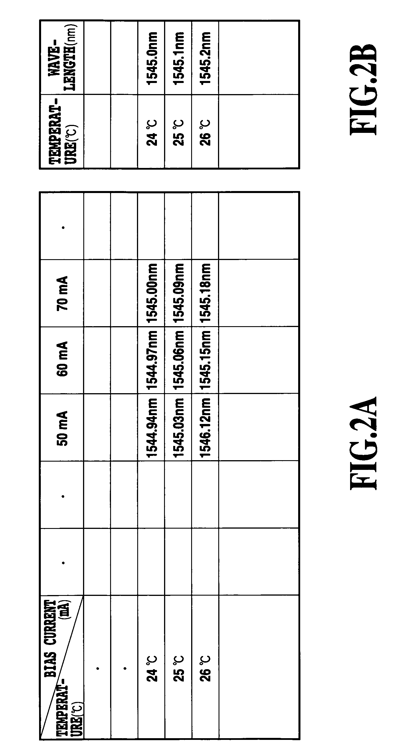
[0016]Thus, with respect to monitoring wavelengths and monitoring and controlling wavelengths by calculating the wavelengths on the basis of the relationship between the LD temperature and bias current and the wavelength and between the LD temperature and wavelengths stored in advance in the storage portion, since the system does not require any complicated optical system in which an etalon filter is used as in the prior art, the structure thereof can be simplified, and reduced size and cost can be expected. For example, even in a Coarse WDM (interval between wavelengths is 1000 GHz through 50 nm, ITU-TG. 694.2) which does not require wavelength monitoring and control, the use of such a wavelength monitoring feature improves reliability in operation management such as enabling a proactive measure against an emergent condition of a system, thus providing a great effect.
[0017]In addition, in terms of the wavelength monitoring and control, by associating the temperature adjustment feature with an external temperature, minimal operation required for the temperature adjustment feature can be achieved when the external temperature exceeds the minimum value or the maximum value of the wavelength threshold, whereby the power consumption can be decreased in comparison with a case where the temperature adjustment feature is operated at all times. Further, by using a temperature control feature, a dense WDM technology can be employed, making it possible to increase the number of wavelengths per a single core. Further, by storing, not a deviation from a predetermined wavelength, but the wavelength itself in a memory, it becomes possible to set an oscillating wavelength to any value within a variable range of the temperature adjusting portion.
[0019]Also, by associating the temperature adjustment feature with an external temperature, minimal operation required for the temperature adjustment feature can be achieved when the external temperature exceeds the minimum value or the maximum value of the wavelength threshold, whereby the power consumption can be decreased in comparison with a case where the temperature adjustment feature is operated at all times.
[0020]By using a wavelength monitoring method in an optical transmitter module or an optical transmitter and receiver module according to the invention, reliability in operation management can be improved by the wavelength monitoring feature. In addition, by using a wavelength monitoring and controlling method in an optical transmitter module or an optical transmitter and receiver module according to the invention, a highly dense WDM technology having narrow intervals between wavelengths can be introduced by the wavelength controlling feature, making it possible to increase the number of wavelengths per a single core in an optical system.

Problems solved by technology

However, where an optical filter such as an etalon is employed for a wavelength monitoring and controlling system, the optical system becomes expensive, and the number of assembling steps is increased, making it difficult to reduce the production costs.
As a result, it is difficult to make the wavelength monitoring and controlling system small in size.
In addition, there is still another problem in that, since the temperature adjusting feature operates at all times to secure a reference temperature, power consumption for adjusting the temperature becomes high.
Therefore, where a change in the wavelength (that is, an amount of the wavelength deviation) depends on factors other than the temperature, sufficient monitoring and control cannot be secured.

Method used


Image

  • Optical module and method for monitoring and controlling wavelengths
  • Optical module and method for monitoring and controlling wavelengths
  • Optical module and method for monitoring and controlling wavelengths

Examples


second embodiment

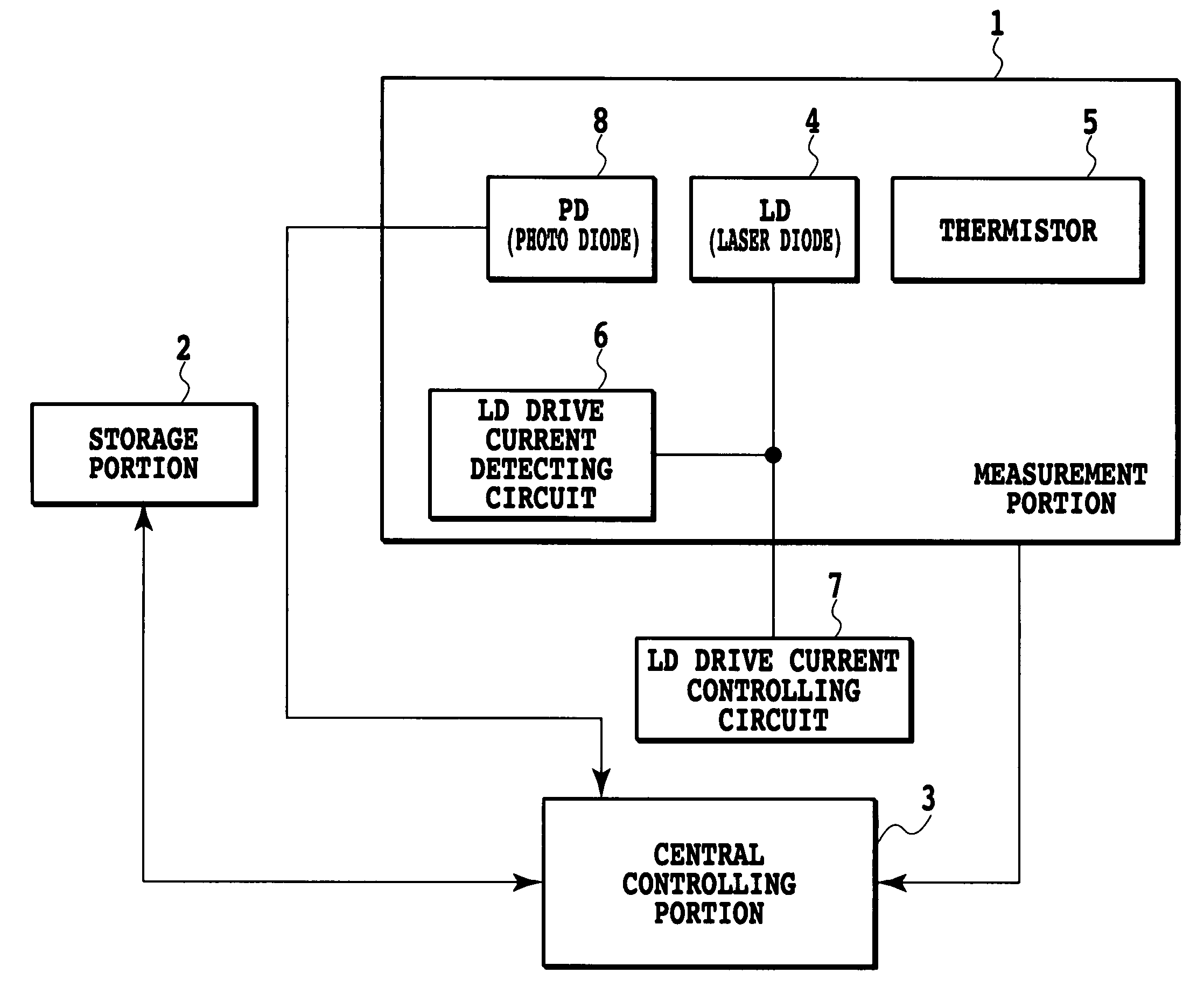
[0044]Next, a description is given of a wavelength monitoring method in an optical transmitter module or optical transmitter and receiver module according to the invention. By setting threshold values related to the wavelengths in the storage portion 2 and comparing the wavelengths calculated by the central controlling portion 3 with the threshold values, it becomes possible to issue an alarm or a warning with respect to wavelength deviation.

[0045]As a detailed example, a description is given of a Small Form Factor Pluggable (SFP) in which an optical portion of a device is formed of a pluggable small-type optical transmitter and receiver module. With respect to the SFP, the wavelength monitoring method is defined in SFP-8472 Revision 9.3 by the SFP Committee. A memory map held by the SFP is illustrated in FIG. 5.

[0046]Herein, threshold values for the alarm and warning are established in an area of 56 bytes in the Alarm and Warning Thresholds addresses 0 through 55 of the storage por...

third embodiment

[0060]Next, a description is given of a wavelength monitoring and controlling method in an optical transmitter module or an optical transmitter and receiver module according to a

[0061]FIG. 8 is a flow chart showing a procedure to describe the wavelength monitoring and controlling method in an optical transmitter module or optical transmitter and receiver module according to the third embodiment. In detail, in the case of SFP, it is necessary to add a temperature adjusting portion.

[0062]First, the temperature, bias current and optical output are measured by the measurement portion 1 (S11). Next, by mapping (S12) in the Real Time Diagnostic Interface of the storage portion 2, the optical output is compared with the minimum threshold value of the optical output warning in the Alarm and Warning Thresholds of the storage portion 2 (S13). When the optical output is smaller than or equal to the minimum threshold value of the optical output warning, the Output Power LOW warning bit in the R...


PUM


Abstract

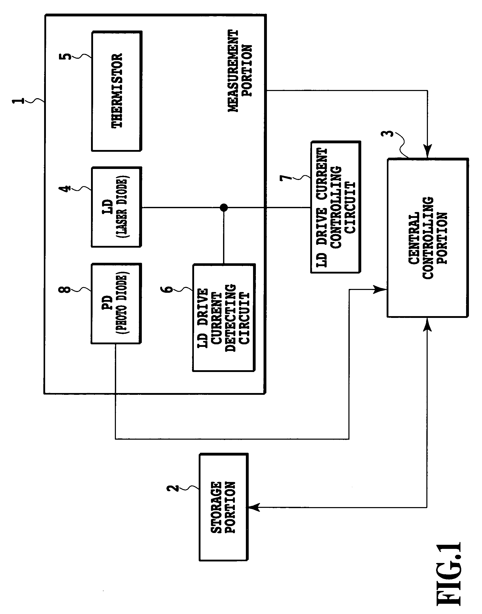
The present invention provides wavelength monitoring and / or control enabling size reduction and low power operation without requiring a complicated optical system in its wavelength monitoring and controlling mechanism.The measurement portion (1) measures temperature by a thermistor (5) in the measurement portion, and measures a bias current by using an LD drive current detecting circuit (6). The LD temperature, optical output and bias current are measured by the measurement portion. The relationship between the LD temperature and wavelengths or between the temperature, bias current and wavelengths is stored in a memory map of the storage portion (2). The central controlling portion (3) calculates wavelengths on the basis of the temperature and the bias current or the temperature information of the measurement portion, and the relationship between the LD temperature, bias current and wavelengths or between the temperature and wavelengths of the storage portion.

Description

TECHNICAL FIELD[0001]The present invention relates to an optical module, a wavelength monitoring method, and a wavelength monitoring and controlling method thereof. In further detail, the invention relates to a wavelength monitoring method in an optical transmitter module and an optical transmitter and receiver module, a wavelength controlling method and a wavelength monitoring and control method in an optical transmitter module and an optical transmitter and receiver module.BACKGROUND ART[0002]In recent years, an increase in the transmission capacity of a transmission line has been demanded in line with an increase in Internet traffic. To meet this demand, a wavelength division multiplexing technology (WDM) which is capable of transmitting data with different wavelengths bundled by a single core fiber has been introduced centering on the core network. Herein, where the WDM technology is employed, an optical coupling and splitting filter having a satisfactory wavelength selection pr...

Claims


Application Information

Patent Timeline
Patent Type & Authority Patents(United States)
IPC IPC(8): H01S5/0687H01S5/042H01S5/068H01S5/0683H04B10/07H04B10/079H04B10/293H04B10/40H04B10/50H04B10/564H04B10/572H04B10/60H04B10/67H04B10/69
CPCH01S5/068H01S5/06804H01S5/06808H01S5/0683
Inventor KAWAI, SHINGOKAWADA, HIDEOYOSHIMOTO, NAOTOOGAWA, TORUIWATSUKI, KATSUMI
Owner NIPPON TELEGRAPH & TELEPHONE CORP
Why Eureka
Try Eureka