Light emitting device and electronic device

a technology of light emitting device and electronic device, which is applied in the direction of static indicating device, organic semiconductor device, instrument, etc., can solve the problems of reducing the yield increasing the layout area, and reducing the aperture ratio of the display panel, so as to achieve the effect of increasing the aperture ratio, low power consumption, and increasing the aperture ratio

Inactive Publication Date: 2008-12-09
SEMICON ENERGY LAB CO LTD
View PDF44 Cites 33 Cited by
  • Summary
  • Abstract
  • Description
  • Claims
  • Application Information

AI Technical Summary

Benefits of technology

[0021]Further, a light emitting device is required in which a voltage of the opposite direction (hereinafter referred to as a reverse bias voltage) is regularly applied to a light emitting element to control degradation of a light emitting element and improve reliability.
[0029]According to the invention, the number of transistors which form pixels and the number of wires such as the scan lines and the power source lines connected to each pixel can be reduced, thereby the aperture ratio can be increased.
[0030]Further, in a light emitting device of the invention, the number of transistors which form pixels and the number of wires such as the scan lines and the power source lines connected to each pixel can be reduced and thus the aperture ratio can be increased. Therefore, a voltage applied to a light emitting element for holding desired luminance can be suppressed, thereby low power consumption can be realized.
[0031]Further, in a light emitting device of the invention having adjacent pixels provided at each intersection of the scan lines and the data lines, a forward bias voltage can be applied to one pixel so that a light emitting element can emit light and a reverse bias voltage can be applied to the other pixel at the same time. Therefore, a period for applying a reverse bias voltage is not required, thus degradation of a light emitting element can be controlled and reliability thereof can be improved without decreasing a duty ratio (a ratio of a light emission period in one frame period).
[0032]Further, in a light emitting device of the invention, a visible pseudo contour which is a problem in displaying an image by the time gray scale method can be reduced by employing a method (an interlace method) for sequentially performing light emission of pixels of every other row in an extending direction of the data lines or the scan lines. Further, a visible pseudo contour can be reduced by employing a method (a checker method) for performing light emission of pixels in what is called a check pattern so that pixels emit light which are one pixel aside of the pixels which emit light in the preceding row in the extending direction of the data lines.
[0033]Further, in an electronic device using a light emitting device of the invention, the number of transistors connected to each pixel, the number of wires such as the scan lines and the power source lines can be reduced as described above, therefore, a layout area of driver circuits in the periphery of a pixel portion can be reduced and a layout area of a display panel can be reduced as well. Accordingly, an electronic device can be downsized and lighter in weight. Further, a product can be manufactured with high yield, and thus more inexpensive product can be provided for customers.

Problems solved by technology

Therefore, such problems as a decrease in the aperture ratio and an increase in power consumption for holding predetermined luminance become more notable in accordance with the increase in the number of transistors which form each pixel.
Accordingly, there are such problems as an increase in a layout area and a decrease in yield of a display panel in accordance with an increase in the number of wiring connections, a decrease in an aperture ratio in accordance with an increase in the number of wires, and an increase in power consumption for holding predetermined luminance.
Further, in the case of performing display by a time division gray scale method in a light emitting device, a pseudo contour occurs and image quality degrades.

Method used


Image

  • Light emitting device and electronic device
  • Light emitting device and electronic device
  • Light emitting device and electronic device

Examples


embodiment mode 1

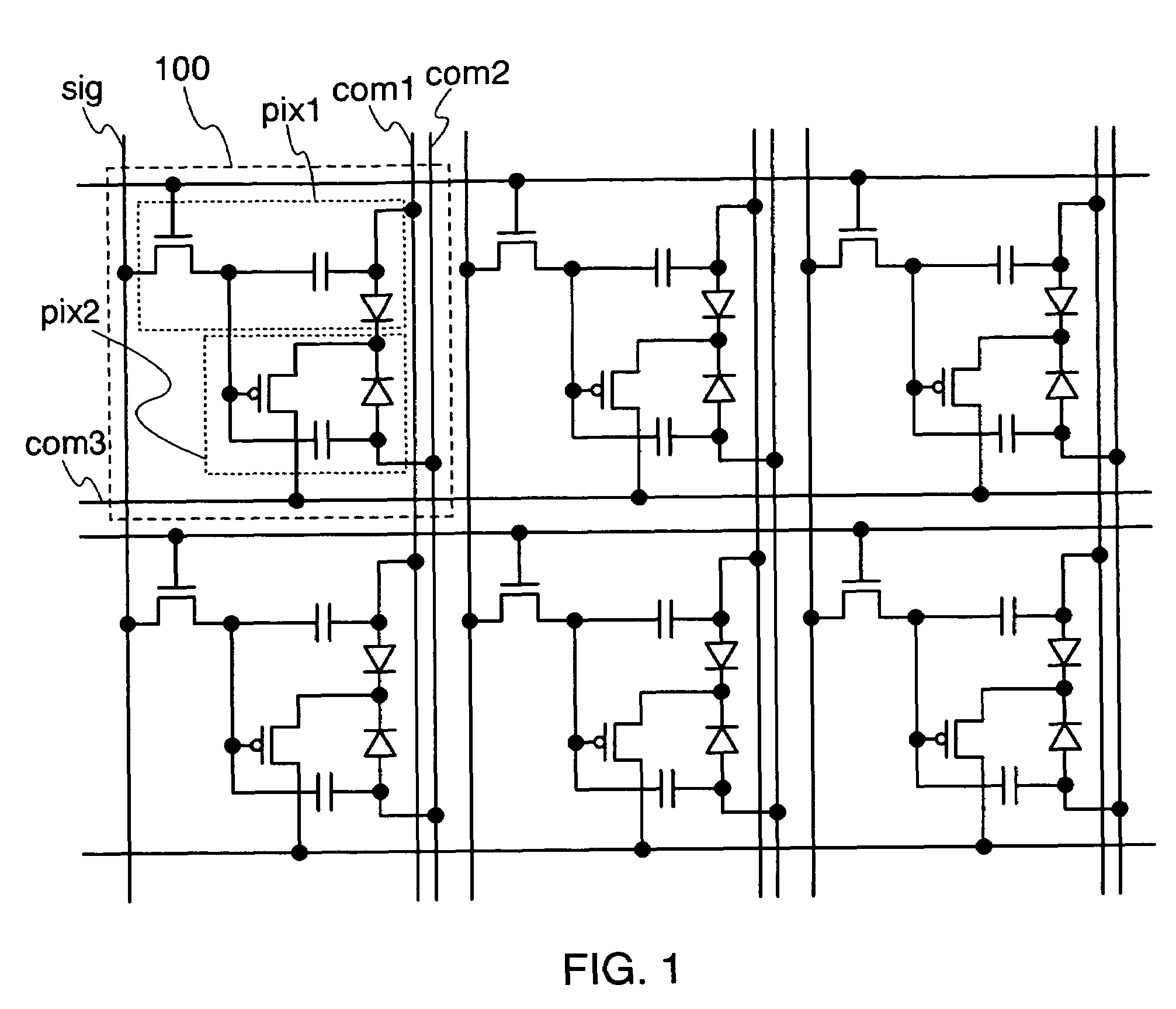
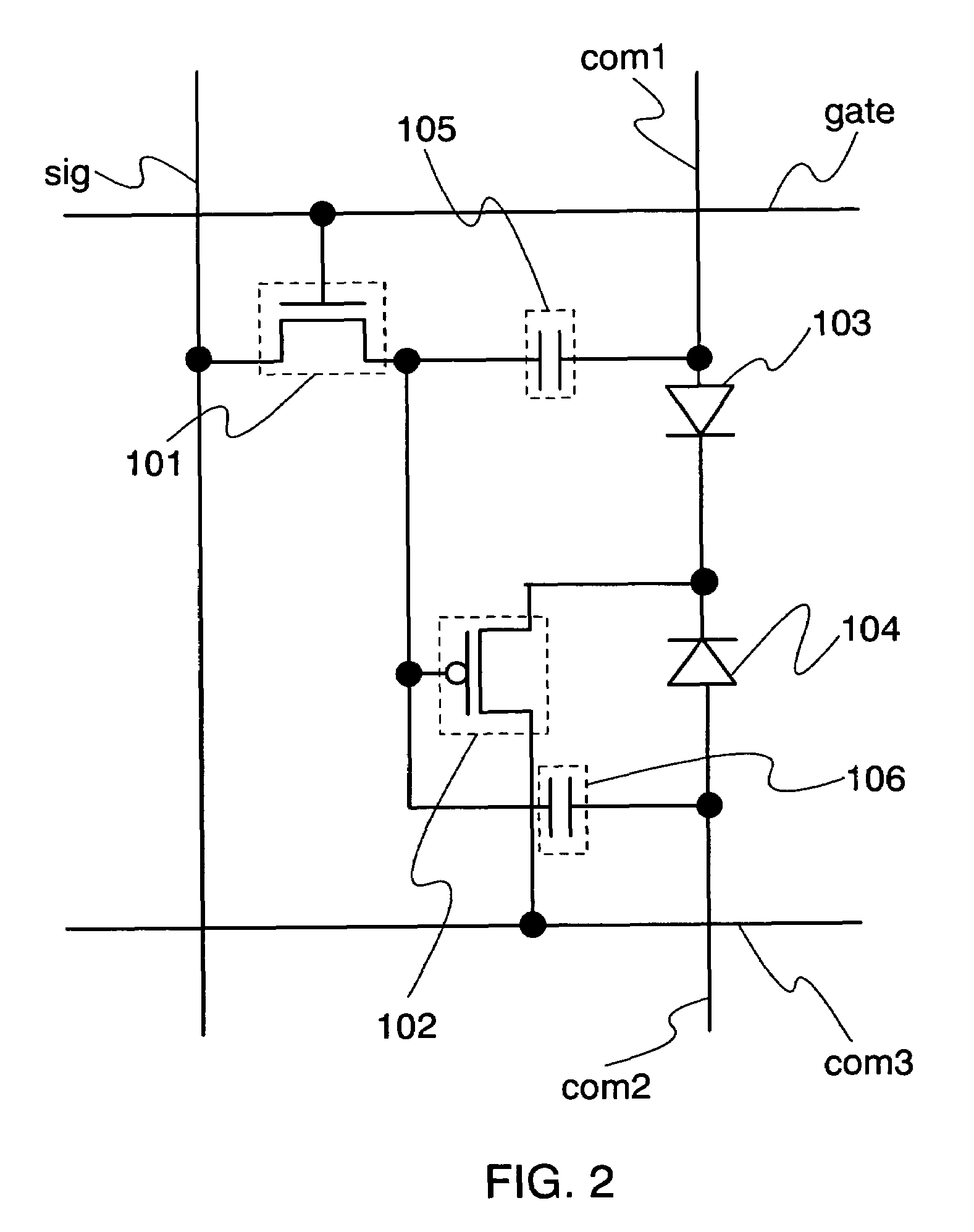
[0077]FIG. 1 shows a circuit diagram in which pixel portions of this embodiment mode are arranged in matrix. FIG. 2 shows an enlarged circuit configuration of a circuit in the pixel portion of this embodiment mode. A region 100 shown in FIG. 1 includes a first pixel pix1 and a second pixel pix2. Further, each of the region 100 shown in FIG. 1 and the enlarged region 100 shown in FIG. 2 includes a scan line gate, a data line sig, a first power source line com1, a second power source line com2, and a third power source line com3.

[0078]It is to be noted in the invention that a pixel portion refers to a region provided at each intersection of a plurality of scan lines and a plurality of data lines. In this embodiment mode, the region 100 corresponds to a pixel portion.

[0079]In FIG. 2, the pixel portion includes a selecting transistor 101, a driving transistor 102, a first light emitting element 103, a second light emitting element 104, a first capacitor 105, and a second capacitor 106.

[...

embodiment mode 2

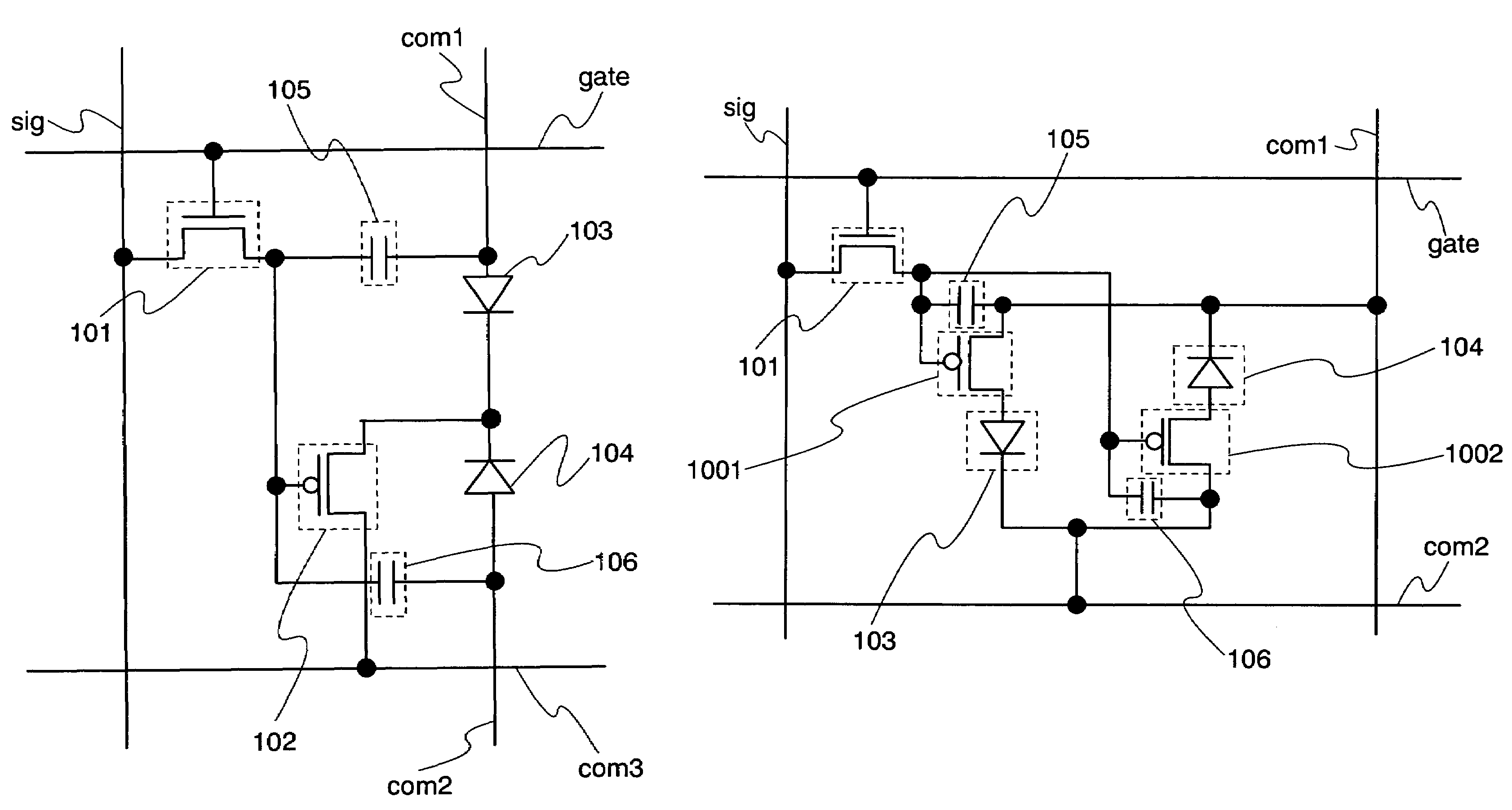
[0127]In Embodiment Mode 1, the description is made on the circuit diagram of the light emitting device where a common driving transistor is driven for both the first light emitting element and the second light emitting element usually, thereby a reverse bias voltage is applied to the second light emitting element while the first light emitting element emits light. In this embodiment mode, a specific configuration where a driving transistor is provided for each of the first light emitting element and the second light emitting element is described below.

[0128]FIG. 9 shows a circuit diagram where pixels of this embodiment mode are arranged in matrix. FIG. 10 shows an enlarged circuit configuration of a pixel portion of this embodiment mode. The region 100 as a pixel portion shown in FIG. 9, which is the pixel portion, includes the first pixel pix1 and the second pixel pix2. Further, each of the regions 100 shown in FIG. 9 and the enlarged region 100 shown in FIG. 10 includes a scan li...

embodiment mode 3

[0152]In the aforementioned embodiment mode, an erasing transistor may be provided for erasing the electrical potentials held in the first capacitor and the second capacitor. Specific configurations thereof are described below.

[0153]FIG. 13 shows a circuit diagram where pixel portions of this embodiment mode are arranged in matrix. FIG. 14A shows an enlarged circuit configuration of the pixel portion of this embodiment mode. The region 100 shown in FIG. 13 includes the first pixel pix1 and the second pixel pix2. Further, each of the region 100 shown in FIG. 13 and the enlarged region 100 shown in FIG. 14A includes a scan line gate1, an erase line gate2, a data line sig, a first power source line com1, and a second power source line com2.

[0154]In FIG. 14A, the pixel portion includes the selecting transistor 101, the first driving transistor 1001, the second driving transistor 1002, an erasing transistor 1401, the first light emitting element 103, the second light emitting element 104...


PUM


Abstract

The invention is made in view of solving problems in reduction in yield and an aperture ratio in accordance with an increase in the number of transistors which form a pixel, increase in power consumption for holding predetermined luminance to provide a light emitting device having a noble pixel configuration. A light emitting device of the invention includes a unit for applying a forward bias voltage to a first light emitting element so that a first pixel emits light and applying a reverse bias voltage to a second light emitting element, and a unit for applying a reverse bias voltage to the first light emitting element so that the first pixel emits no light and applying a forward bias voltage to the second light emitting element.

Description

BACKGROUND OF THE INVENTION[0001]1. Field of the Invention[0002]The present invention relates to an active matrix light emitting device using a light emitting element having a film containing an organic compound (hereinafter referred to as an organic compound layer) between a pair of electrodes which provides fluorescence or phosphorescence when applied an electric field by a TFT (Thin Film Transistor). It is to be noted that a light emitting device in this specification refers to an image display device, a light emitting device, or a light source. Further, a module in which a light emitting element is provided with a connector, for example an FPC (Flexible Printed Circuit), a TAB (Tape Automated Bonding) tape, a TCP (Tape Carrier Package), a module in which the tip of a TAB tape or a TCP is provided with a printed wiring board, and a module in which an IC (Integrated Circuit) is directly mounted to a light emitting element by a COG (Chip On Glass) method are all included in a light...

Claims


Application Information

Patent Timeline
Patent Type & Authority Patents(United States)
IPC IPC(8): H01L31/062H01L31/113
CPCG09G3/3233H01L27/1292H01L27/3244H01L27/12G09G2300/0852G09G2310/0224G09G2310/0262H01L2251/5315H01L2251/5323H01L2251/564H10K59/12H10K2102/3031H10K2102/3026H10K71/841
Inventor ENDO, MASAMI
Owner SEMICON ENERGY LAB CO LTD
Why Eureka
Try Eureka