Error driven RF power amplifier control with increased efficiency
a power amplifier and efficiency technology, applied in the direction of amplifier modification to reduce noise influence, gain control, supply voltage varying control, etc., can solve the problems of increasing the efficiency of pa 104, sacrificing power during the off-peak of amplitude, undesirable wide spectral occupancy, etc., to increase the efficiency of the power amplifier, and reduce the supply voltage
- Summary
- Abstract
- Description
- Claims
- Application Information
AI Technical Summary
Benefits of technology
Problems solved by technology
Method used
Image
Examples
first embodiment
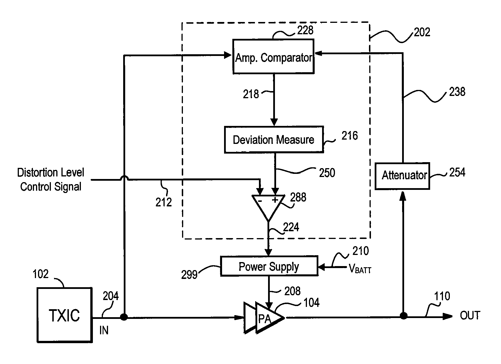
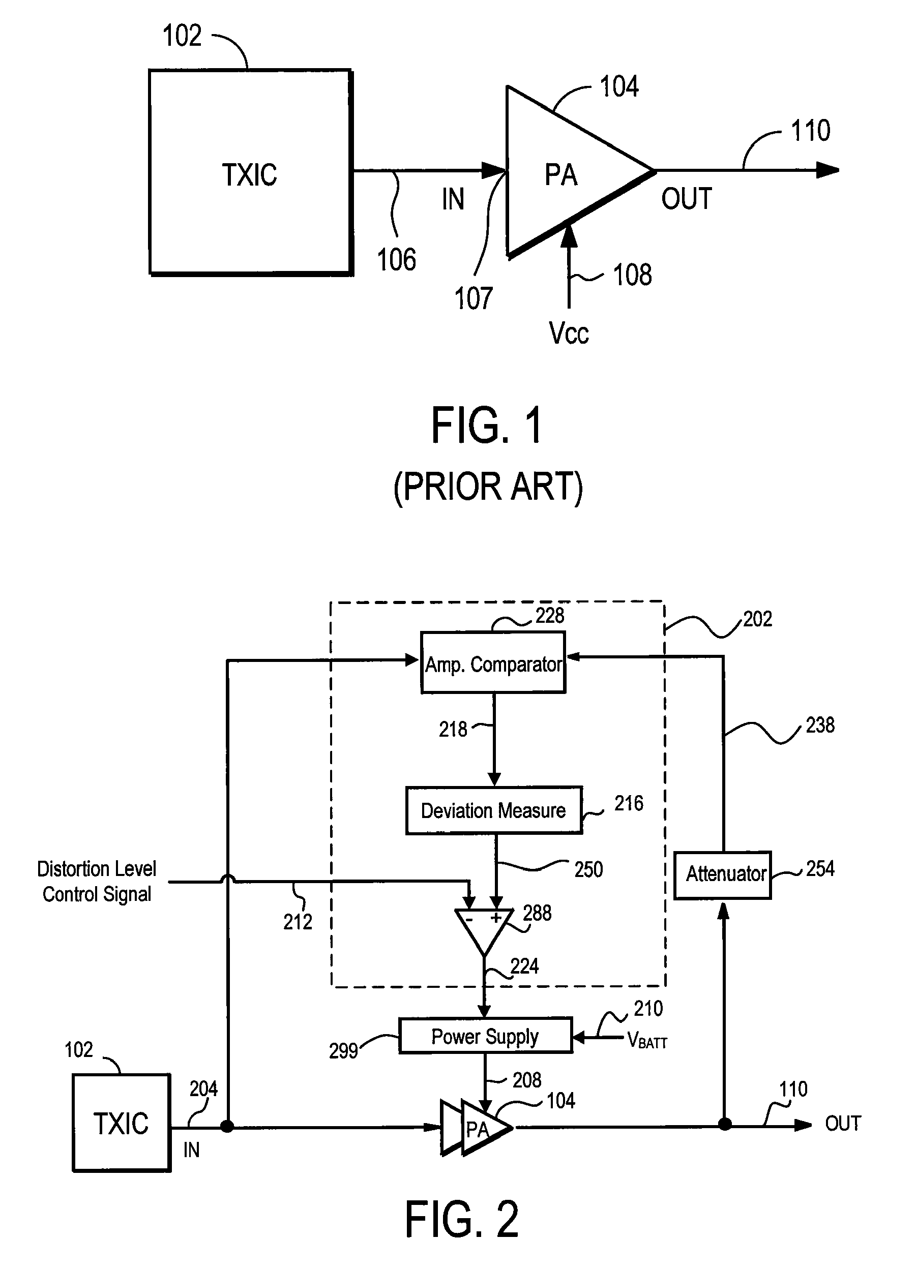
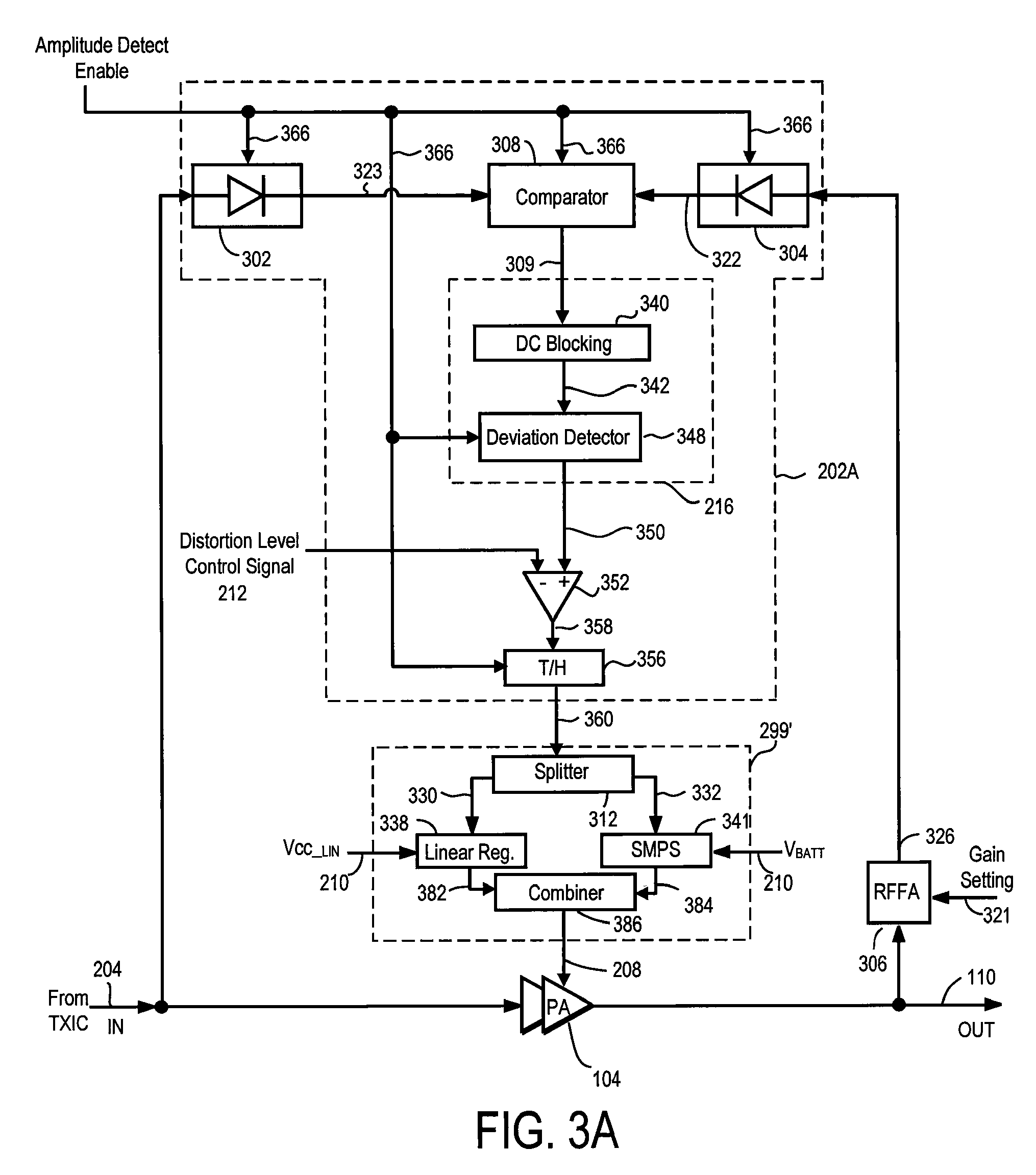
[0041]FIG. 3A illustrates an RF PA system, according to the present invention. The RF PA system includes, among other components, the PA 104, the PA controller 202A, an adjusted variable attenuator (RFFA (RF Feedback Attenuator)) 306, and a power supply 299′. The PA controller 381 includes, among other components, a comparator 308, a DC blocking module 340, a deviation detector 348, an error amplifier 352, a track and hold (T / H) module 356, and two matched amplitude detectors 302, 304. The power supply 299′ may include a splitter 312, a linear regulator 338, a switched-mode power supply (SMPS) 341, and a power combiner 386.
[0042]Referring to FIG. 3A, the amplitude of the RF input signal 204 is monitored through the amplitude detector 302 and compared by the comparator 308 with the amplitude of the RF input signal 110 as attenuated 326 by the adjusted variable attenuator (RFFA) 306, seen through a matched amplitude detector 304. Note that the amplitude detectors 302, 304 and the comp...
case 2
[0046] Comparator 308 Generates Difference Between Logarithms of Amplitudes:
cout(t)=log(A*(s(t)+e(t))−log s(t)
=log A+log(s(t)+e(t))−log s(t)
=log A+log(s(t)+e(t) / s(t))
where cout(t) is the amplitude error signal 309, s(t) is the RF input signal 204, A is the static ratio between the amplitudes of the RF input signal 204 and attenuated RF output signal 326 as detected by detectors 302, 304, and e(t) is the error added by the PA 104 to the RF input signal 204. If the RFFA 306 is adjusted accurately such that the RF output signal 110 of the PA 104 is attenuated to have an amplitude level corresponding to the amplitude level of the RF input signal 204, the value of A approaches 1. In CASE 1, any deviation from A=1 affects the amplitude error signal 309 cout(t), thus requiring the RFFA 306 to be accurately adjusted to discern an accurate estimation of distortion by the deviation detector 348. In CASE 2, the term log A, which is a DC (Direct Current) term, can be removed by a highpass filte...
PUM
 Abstract
Description
Claims
Application Information
 - R&D
- Intellectual Property
- Life Sciences
- Materials
- Tech Scout
- Unparalleled Data Quality
- Higher Quality Content
- 60% Fewer Hallucinations
Browse by: Latest US Patents, China's latest patents, Technical Efficacy Thesaurus, Application Domain, Technology Topic, Popular Technical Reports.
© 2025 PatSnap. All rights reserved.Legal|Privacy policy|Modern Slavery Act Transparency Statement|Sitemap|About US| Contact US: help@patsnap.com


