
Method and device for long-range guided-wave inspection of fire side of waterwall tubes in boilers

Active Publication Date: 2009-01-06
SOUTHWEST RES INST
View PDF13 Cites 21 Cited by
  • Summary
  • Abstract
  • Description
  • Claims
  • Application Information

AI Technical Summary

Benefits of technology

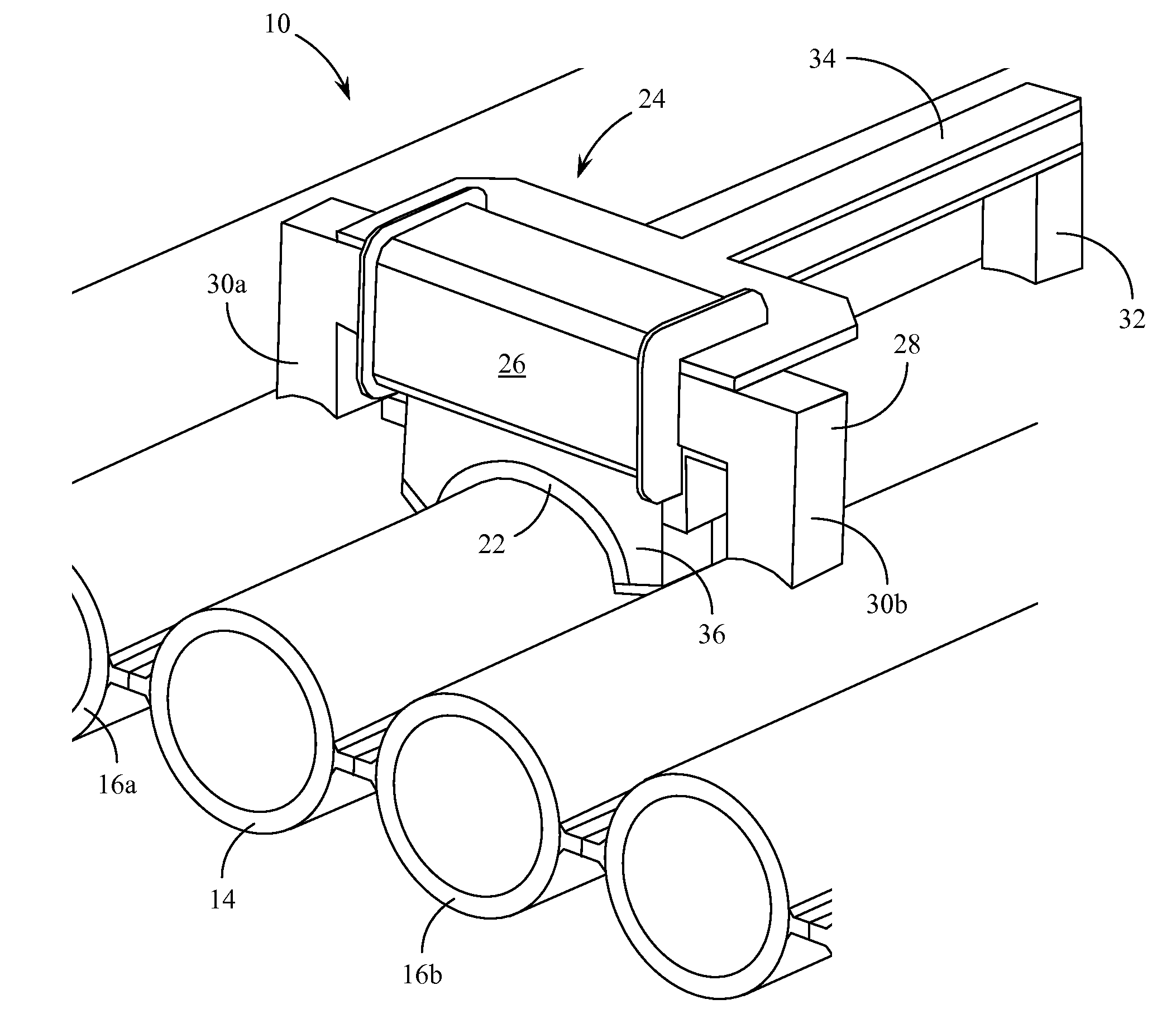
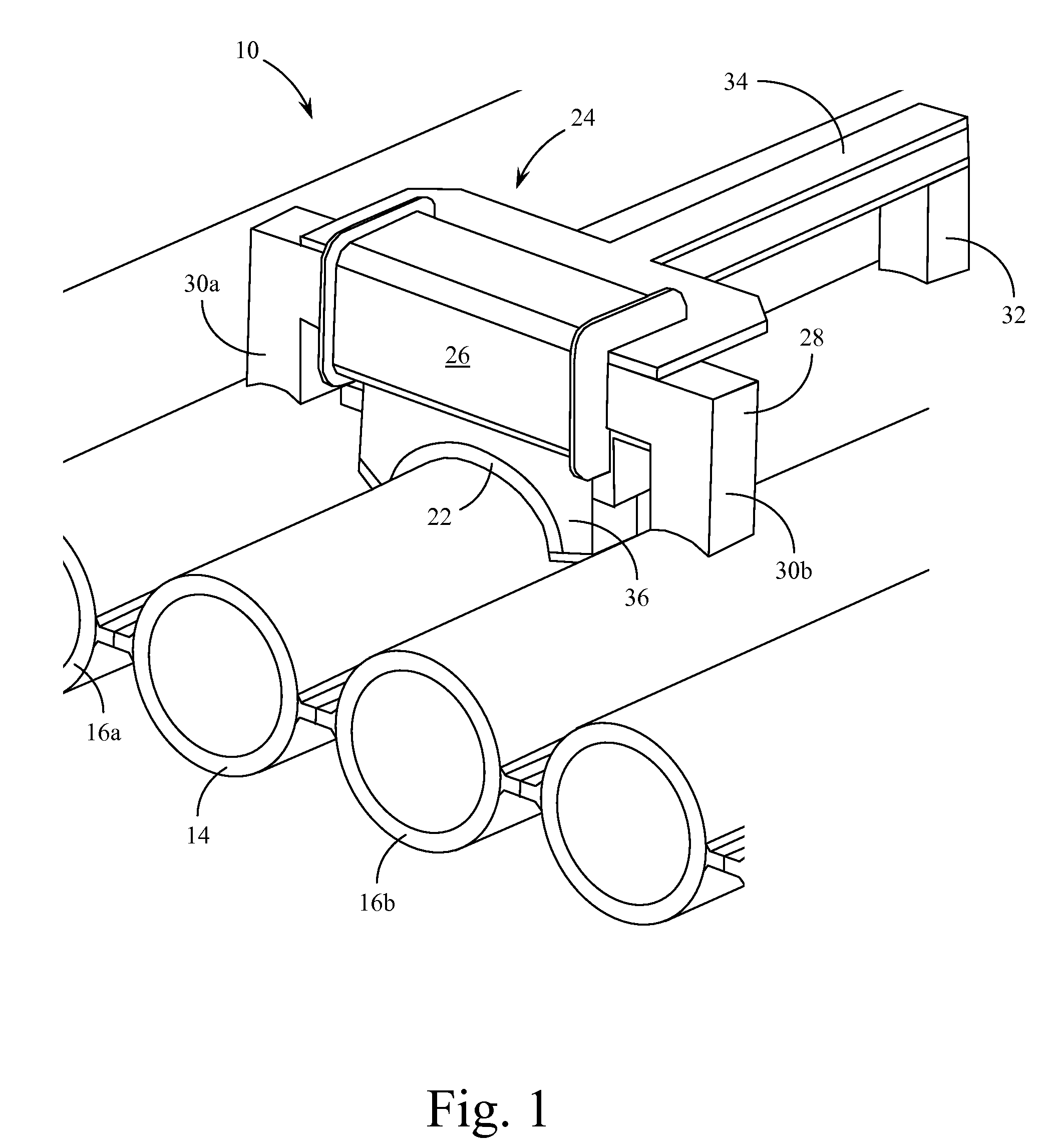
[0018]The system of the present invention uses a magnetostrictive strip and a flat coil-type plate magnetostrictive sensor (MsS) that are held in place on the waterwall using a specially designed frame and an electromagnetic circuit. The magnetostrictive strip and plate type MsS are positioned against a tube in the waterwall using an elastomeric pad or a fluid (air or liquid) filled bladder to achieve close contact and good mechanical coupling between the magnetostrictive strip and the tube surface. When current activated, the electromagnet holds the entire assembly in place and provides a DC bias magnetic field required for plate magnetostrictive sensor probe operation. Long-range guided-waves are pulsed into the tube and reflected signa

Problems solved by technology

The most common cause of forced outage of fossil fuel powered generating units is boiler tube failure.
The majority of these failures occur within the furnace waterwall tubes.
Various damage mechanisms are known to occur that lead to tube failures through wall loss and cracking.
Most of the damage to waterwall tubes occurs on the fire side of the tube by way of wall thinning due to corrosion and / or erosion that results from the furnace exposure and the presence of corrosive gases in the fuel burning process.
Since the boiler waterwall is a very large structure and ultrasonic wall-thickness measurements are time consuming, thickness measurements are typically taken at several points along the height of the wall.
As a result, the reliability of the current decision making process is less than desired and carries a substantial risk of error.
When access is limited to only a portion of the piping circumference, the long-range guided-wave inspection method is difficult to apply.
Waterwall tubes constructed in boiler furnaces present just such an environment where access to the full circumference of an individual tube is not possible.
As indicated above, such inspections are typically carried out using ultrasonic sensors and methodologies, although the limited range of such sensors requires sampling techniques to be utilized during testing.
Very little effort has been made to create sensor structures appropriate for directing long-range guided-waves into such pipe walls, primarily because of the inability to fully encircle the circumference of the individual pipes.
That is, none of the previous efforts that utilize partial circumferential orientation have provided suitable sensor adherence structures for long-range guided-wave inspection purposes.
No sensor structures have been designed that can take advantage of the volumetric inspection capabilities of long-range guided-waves where access to the entire circumference of the pipe or tube is restricted.
EMAT sensors, such as described in the above U.S. patents, are limited in that they fail to achieve the volumetric inspection capabilities of long-range guided-waves.

Method used


Image

  • Method and device for long-range guided-wave inspection of fire side of waterwall tubes in boilers
  • Method and device for long-range guided-wave inspection of fire side of waterwall tubes in boilers
  • Method and device for long-range guided-wave inspection of fire side of waterwall tubes in boilers

Examples


Embodiment Construction

[0025]In general, a preferred method and apparatus for inspecting waterwall tubes for fire side damage according to the present invention, may be summarized as follows:

[0026](a) The placement of a plate type magnetostrictive sensor (MsS) guided-wave probe on the fire side of a waterwall tube, that operates in shear-horizontal (SH) wave mode or, equivalently, torsional (T) wave mode within the tube.

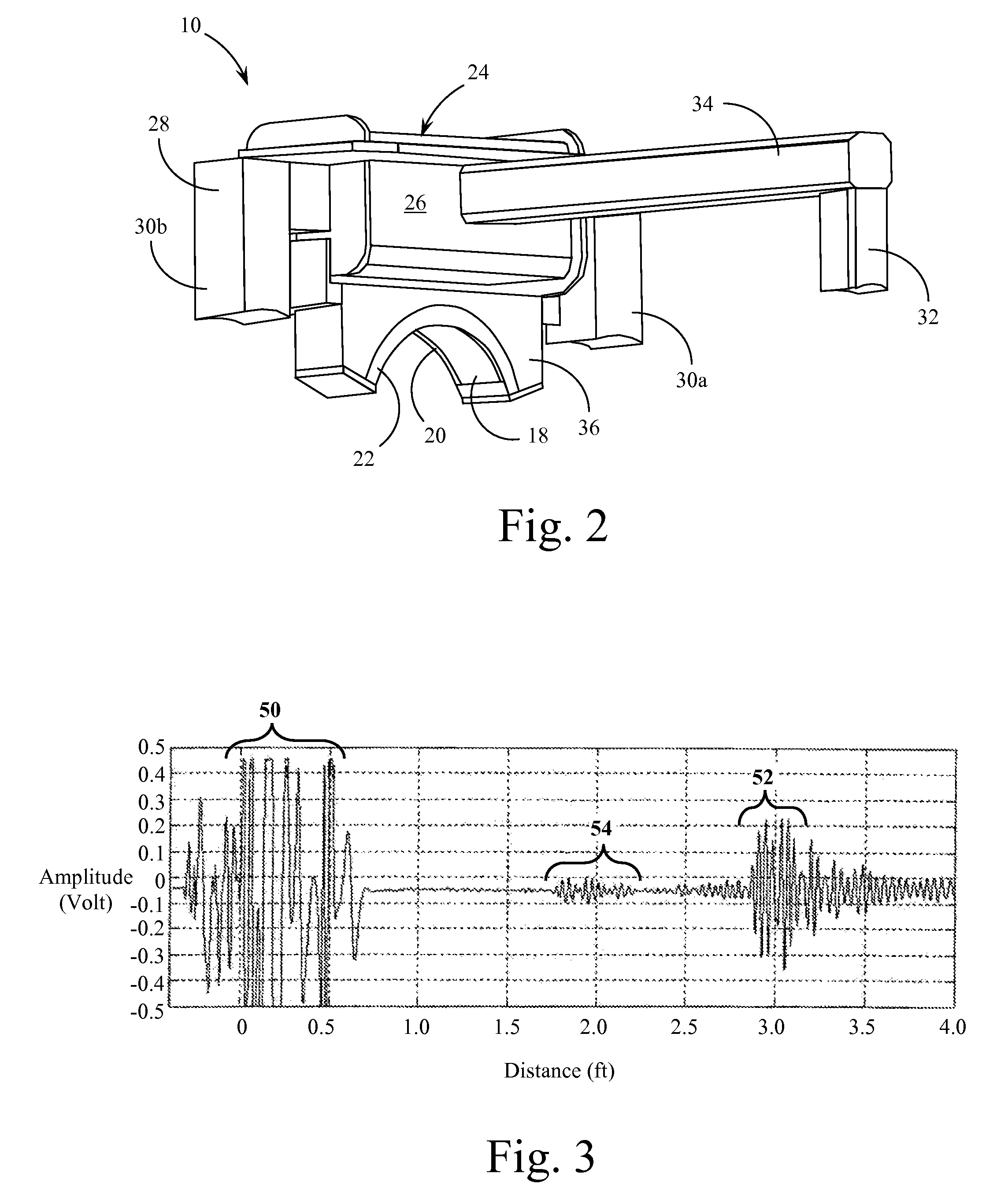
[0027](b) The mechanical coupling of the probe to the tube and the launching of a pulse of guided-waves to one side of the probe (such as upward) along the tube length and the detection of signals reflected from that side. The process is then repeated to launch waves to the other side of the probe (such as downward) and detect the signals reflected from that side.

[0028](c) The analysis of the received signal data for anomalies and defects (cracks, fractures, wall-thinning, etc.).

[0029]The various drawing figures briefly described above illustrate schematically a device for inspecting water...


PUM


Abstract

Methods and devices for inspecting waterwall tubes for the detection of fire side damage over a long length of the tube are described. The system of the invention uses a magnetostrictive strip and a flat coil-type plate magnetostrictive sensor (MsS) that are held in place on the waterwall using a specially designed frame and an electromagnetic circuit. The magnetostrictive strip and plate type MsS are positioned against a tube in the waterwall using an elastomeric pad or a fluid filled bladder to achieve close contact and good mechanical coupling between the magnetostrictive strip and the tube surface. When current activated, the electromagnet holds the entire assembly in place and provides a DC bias magnetic field required for plate magnetostrictive sensor probe operation. Long-range guided-waves are pulsed into the tube and reflected signals are detected within the same sensor structure. The received signal data representative of a long section of the tube under investigation is then analyzed for the presence of anomalies and defects. When data acquisition for a particular tube or tube section is completed the electromagnet is turned off and the entire device is moved to the next tube in the waterwall.

Description

BACKGROUND OF THE INVENTION[0001]1. Field of the Invention[0002]The present invention relates generally to methods and systems for non-destructive testing and inspection of pipes, tubes, and other longitudinal cylindrical structures. The present invention relates more specifically to methods and systems for accurately positioning long-range torsional guided-wave inspection sensors on waterwall tubes in boiler structures and the like.[0003]2. Description of the Related Art[0004]Most fossil fuel based power generating systems utilize the heat released from burning the fuel to convert water to high pressure steam that is then used to turn a steam turbine connected to an electrical generator. One of the most efficient ways of heating water to convert it to steam involves the use of a waterwall boiler wherein the fuel is burned within a confined furnace space defined by walls made up of an array of water tubes. As relatively cool water passes through the tubes it absorbs the heat from th...

Claims


Application Information

Patent Timeline
IPC IPC(8): G01N27/82G01N27/00G01R33/18
CPCG01N29/043G01N29/226G01N29/2412G01N29/265G01N29/28G01R33/18G01N2291/0422G01N2291/044G01N2291/2634G01N2291/2695
Inventor KWUN, HEGEONMATSUMOTO, HIROTOSHICRANE, JAMES F.
Owner SOUTHWEST RES INST
Learn More