Micro-optic adapters and tips for surgical illumination fibers

a technology of optical adapters and fibers, applied in waveguides, applications, instruments, etc., can solve the problems of fragile end product, unprotected modified section, expensive techniques for polishing or manipulating tips,

Active Publication Date: 2009-01-06
INVUITY
View PDF2 Cites 47 Cited by
  • Summary
  • Abstract
  • Description
  • Claims
  • Application Information

AI Technical Summary

Benefits of technology

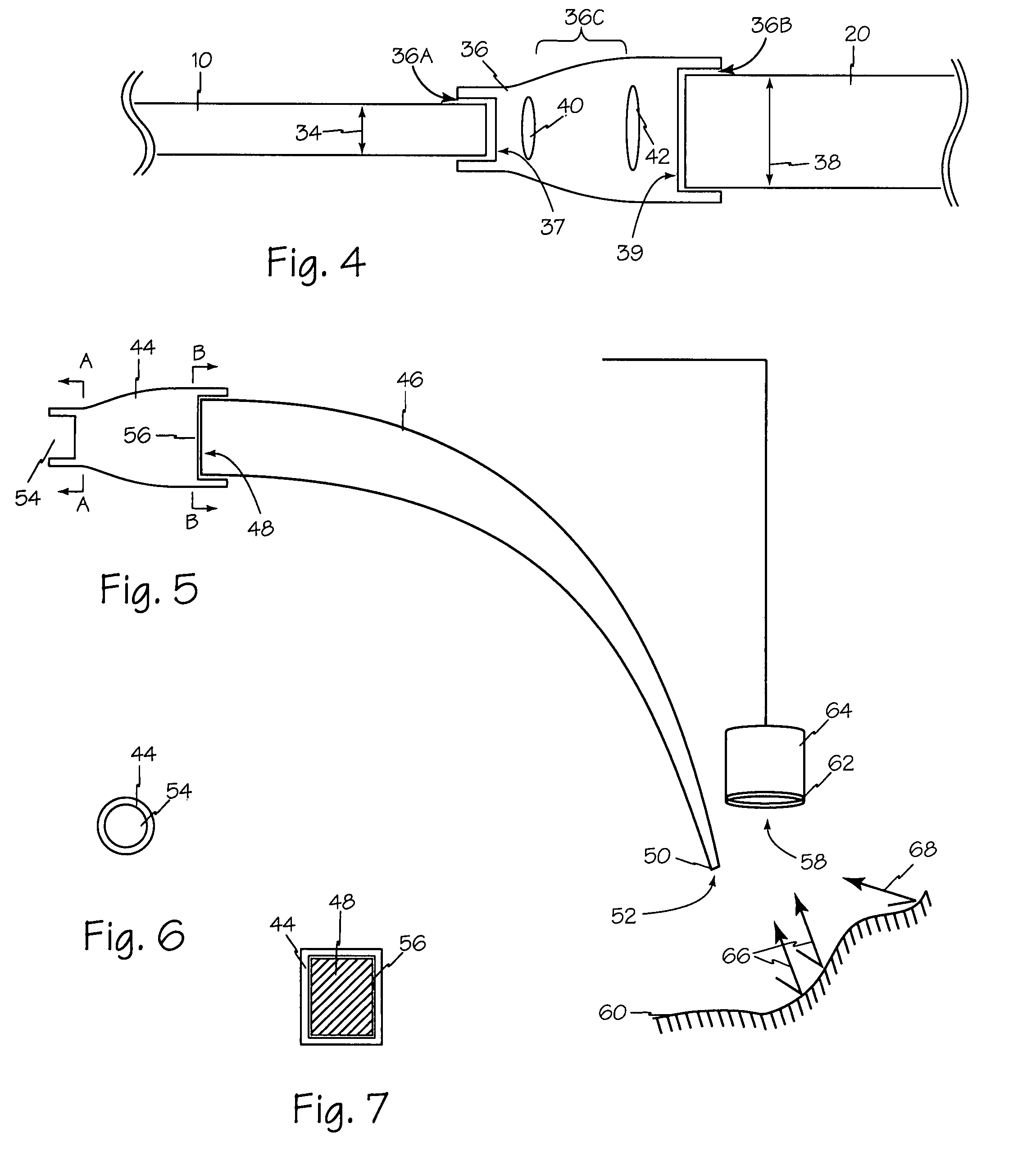
[0007]A micro structured optical adapter or tip according to the present disclosure may incorporate optical lensing structures to be placed over the end of any suitable illumination device such as fiber optic laser delivery devices. The cap or adapter may incorporate micro structured optical components such as for example gratings, prisms and or diffusers to operate as precision optics for customized delivery of the light energy. These components may be formed as injection molded plastic or glass parts to allow for inexpensive modification of the output light and also serve to protect the end of the device, such as a cleaved fiber optic bundle. The micro structured optical components may also be incorporated in an adapter to tailor the light energy to the subsequent devices. The micro structured optical components may also be used to polarize and / or filter the light energy entering or exiting the illumination device.

Problems solved by technology

The limitation of these techniques is that they require accurate manipulation of the device resulting in a modified section which is then left unprotected.
For optical fibers, the techniques for polishing or manipulating the tip are costly, time consuming and result in a fragile end product.
The techniques available for creating lensing surfaces using the device itself are limited and generate limited optical output lensing options.
In these settings, focus of the laser beam emanating from the fiber is difficult to control due to the similar indices of refraction of the various media and the fiber.

Method used


Image

  • Micro-optic adapters and tips for surgical illumination fibers
  • Micro-optic adapters and tips for surgical illumination fibers
  • Micro-optic adapters and tips for surgical illumination fibers

Examples


Embodiment Construction

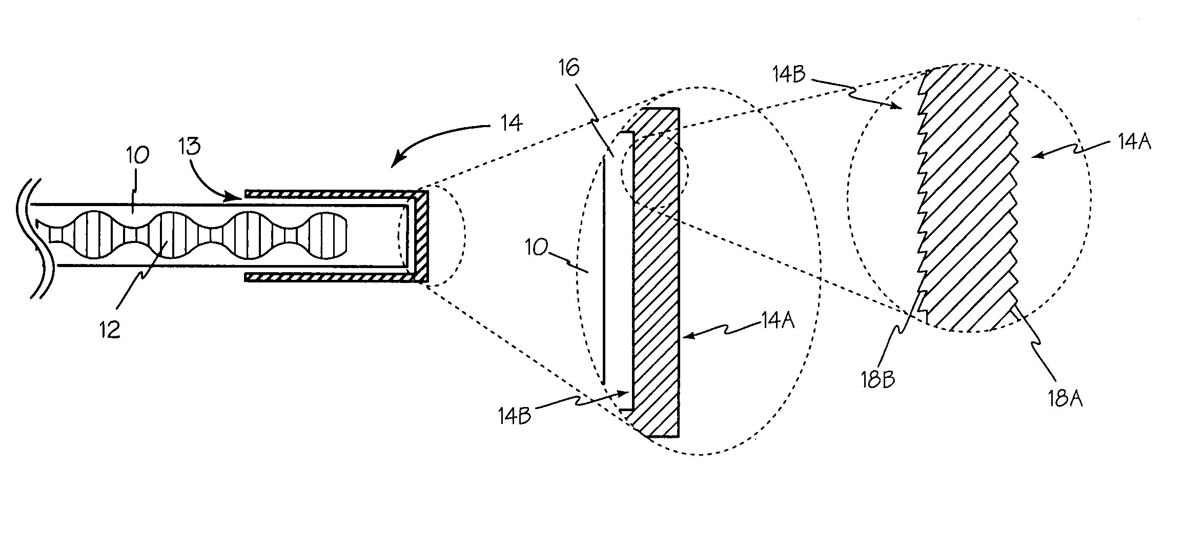
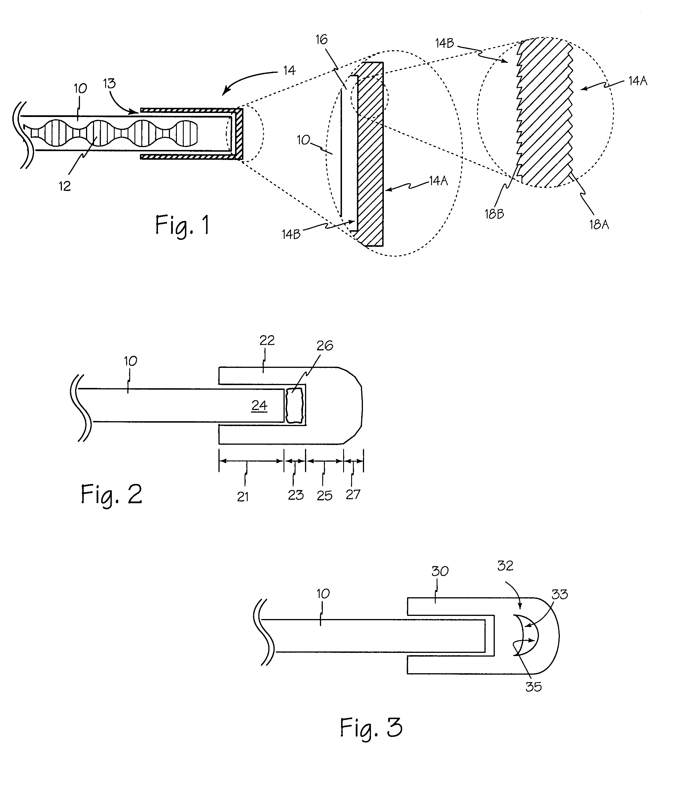
[0016]In FIG. 1 medical illumination fiber 10 engages an end cap such as cap 14 to form an optical path with one or more micro structure optical surfaces such as inner optical surface 14A or outer optical surface 14B and or one or more air gaps such as gap 16 and or index matching material to control light 12. Any suitable surface such as inner an outer optical surfaces 14A and 14B or a portion of an inner or outer surface may be formed to include micro structure optical structures such as structure 18A and or 18B thereon. Cap 14 may be made of glass, plastic or any other suitable material and may be sized to enable bore 13 to frictionally engage optical fiber 10.

[0017]Input and or output micro optical structures such as structure 18A or structure 18B may adopt any suitable configuration to accomplish one or more of the functions of diffracting, deflecting, refracting or polarizing light passing through the micro structure optical component. Such structures individually or in combin...


PUM


Abstract

A microstructure optical adapter or tip according to the present disclosure may incorporate precision micro structure optical components engaging the input or output end of light energy delivery devices for customized light delivery of the light energy. The incorporation of precision micro structure optical components in injection molded plastic or glass parts will allow for inexpensive modification of the output light while also serving to protect the end of the illumination device. The micro structure optical components may also be incorporated in an adapter to tailor the light energy to the subsequent device.

Description

RELATED APPLICATIONS[0001]This application claims priority from copending U.S. Provisional patent application 60 / 795,986 filed Apr. 27, 2006.FIELD OF THE INVENTION[0002]The inventions described below relate to the field of surgical illumination and more specifically to Micro Structured Optical adapters and end caps for surgical illumination.BACKGROUND OF THE INVENTION[0003]Illumination devices, such as fiber optics, have many applications and generally employ conventional methods such as reflective surfaces or total internal reflection to deflect or focus the light energy. Some devices also have modifications of the distal end or tip geometry to generate focused or defocused beams. Tip modifications for optical fibers are typically produced by polishing or grinding of the fiber tip or the end of a bundle of fibers. Conventional techniques have also included use of high temperatures such as with use of a fusion splicer to create ball tip structures generated by melting the core of an...

Claims


Application Information

Patent Timeline
Patent Type & Authority Patents(United States)
IPC IPC(8): G02B6/26
CPCG02B6/241G02B6/262G02B6/34A61B1/07A61B2018/2261G02B6/32Y10S385/901Y10S385/902A61B90/30A61B2090/3614G02B6/0008G02B23/2423G02B23/2469A61B2090/306
Inventor VAYSER, ALEXTRAUNER, KENNETH C.
Owner INVUITY
Why Eureka
Try Eureka