Microfluidics devices and methods of diluting samples and reagents

a technology of microfluidics and reagents, applied in the field of microminiaturization of genetic, biochemical and bioanalytic processes, can solve the problems of reducing optical signals, affecting the accuracy of microfluidics results, so as to reduce reduce the reaction time and the amount of biological materials, and eliminate experimental errors. , the effect of reducing the cost of reagents

Inactive Publication Date: 2009-01-13
TECAN TRADING AG
View PDF8 Cites 27 Cited by
  • Summary
  • Abstract
  • Description
  • Claims
  • Application Information

AI Technical Summary

Benefits of technology

[0027]The present invention solves problems in the current art through the use of a microfluidic disc in which centripetal acceleration is used to move fluids. It is an advantage of the microfluidics platforms of the present invention that the fluid-containing components are constructed to contain a small volume, thus reducing reagent costs, reaction times and the amount of biological material required to perform an assay. It is also an advantage that the fluid-containing components are sealed, thus eliminating experimental error due to differential evaporation of different fluids and the resulting changes in reagent concentration. Because the microfluidic devices of the invention are completely enclosed, both evaporation and optical distortion are reduced to negligible levels. The platforms of the invention also advantageously permit “passive” mixing and valving, i.e., mixing and valving are performed as a consequence of the structural arrangements of the components on the platforms (such as shape, length, position on the platform surface relative to the axis of rotation, and surface properties of the interior surfaces of the components, such as wettability as discussed below), and the dynamics of platform rotation (speed, acceleration, direction and change-of-direction), and permit control of assay timing and reagent delivery.
[0028]The disclosed invention also provides microfluidic disc comprising metering structures and a microfluidic network that is used to distribute aliquots of reagent to each of a multiplicity of mixing structures, each mixing structure being fluidly connected to one of a multiplicity of sample reservoirs, thereby permitting parallel processing and mixing of the samples with one or more common reagents. The fluidic network, defined as the overall pattern of channels, reservoirs, microvalves, and air vents, may be planar or three-dimensional, depending upon the application under consideration. The use of such metering and distribution reduces the need for automated reagent distribution mechanisms, reduces the amount of time required for reagent dispensing (that can be performed in parallel with distribution of reagent to a multiplicity of reaction chambers), and permits delivery of small (nL-to-μL) volumes without using externally-applied electromotive means.

Problems solved by technology

However, a number of problems arise-when miniaturizing standard plate technology.
First, because the total volumes are smaller and the plates are open to the environment, evaporation of fluid during the course of an assay can compromise results.
Another drawback of open plates is the existence of a fluid meniscus in the well.
As the strength of the optical signals decreases with decreasing assay volume, correction for background distortions becomes more difficult.
Finally, optical scanning systems for high-density plates are often complex and expensive.
Serial pipetting defeats the aim of parallelism by increasing the amount of time required to address the plate.
Integration of microdevices with existent laboratory infrastructure is also desirable and has been poorly addressed in the art.
Fluid processing in microtiter plates is also difficult.
For similar reasons, washing, an important step in many assays can be problematic.

Method used


Image

  • Microfluidics devices and methods of diluting samples and reagents
  • Microfluidics devices and methods of diluting samples and reagents
  • Microfluidics devices and methods of diluting samples and reagents

Examples


example 1

Simultaneous Enzyme Inhibition Assays

[0195]A platform depicted in the FIG. 11 was used in this example. The platform of FIG. 11 is functionally identical to that of FIGS. 1-8, the only significant difference being that that of FIG. 11 is designed for the performance of 24 assays, while that of FIGS. 1-8 is designed for the performance of 96 assays.

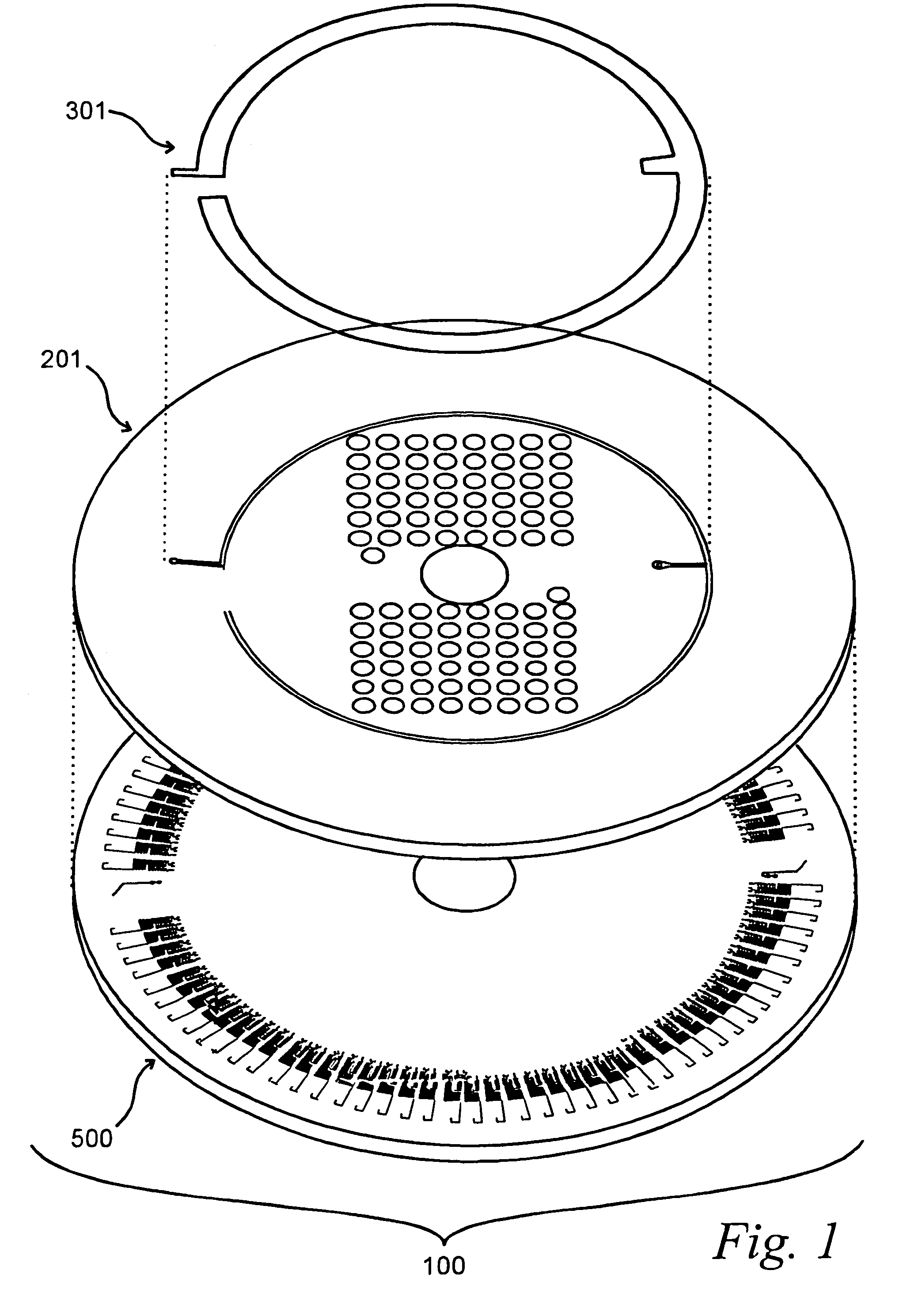
[0196]The platform was prepared as follows. The microfluidic reservoir layer 201 was manufactured through machining of acrylic using computer / numerical code machining using a Light Machines VMC5000 milling machine running Light Machines “Benchman” software (Light Machines Corporation, Manchester, N.H.).

[0197]The sealing film of as shown in FIG. 3 was made by applying a double-sided tape to a thin sheet of heat-stabilized polyester (mylar). A section of mylar bonded to tape was cut from the combined sheet to the correct shape, leaving one adhesive face of the tape for application to the macrofluidic layer.

[0198]The microfluidics layer was m...

example 2

Dilution Methods

[0225]A microsystem platform as shown in FIG. 17 was used to dilute a fluorescein-containing sample. This test was performed in two stages. First 1 mM fluorescein in DMSO was used to assess the performance of the first stage. Next 20 mM fluorescein in DMSO was used to assess the performance from the 4th dilution to the 9th. The 20 mM fluorescein experiments were necessary to resolve the concentrations at the higher dilution range, which were not detectable using 1 mM fluorescein.

[0226]Meter chamber and intermediate cuvette volumes as well as theoretical dilution ratios for 1st stage dilution structures are shown in Table 1.

[0227]

TABLE I1st Stage characteristics5thNon-1st2nd3rd4thDilution / meteredDilutionDilutionDilutionDilutionReservoirMeter (μl)0.00.63570.21470.06710.02100.0153Meter Dimensions10888 × 200 × 2883926 × 200 × 2611582 × 200 × 1901847 × 127 × 851652 × 127 × 71.5L × W × D (μm)Intermediate (μl)*2.01.36871.79111.93641.98445.1439Theoretical0.03.17 · 10−11.07 ·...


PUM

PropertyMeasurementUnit
depthaaaaaaaaaa
volumesaaaaaaaaaa
volumesaaaaaaaaaa

Abstract

This invention relates to methods and apparatus for performing microanalytic and microsynthetic analyses and procedures. The invention provides a microsystem platform and a micromanipulation device for manipulating the platform that utilizes the centripetal force resulting from rotation of the platform to motivate fluid movement through microchannels. These assays may be performed for a variety of purposes, including but not limited to screening of drug candidate compounds, life sciences research, and clinical and molecular diagnostics. Methods specific for the apparatus of the invention for performing any of a wide variety of microanalytical or microsynthetic processes are provided.

Description

[0001]This application claims priority to U.S. Provisional Applications Serial Nos. 60 / 436,335 and 60 / 436,384, each filed Dec. 24, 2002, the disclosure of each of which is explicitly incorporated by reference herein.BACKGROUND OF THE INVENTION[0002]1. Field of the Invention[0003]This invention relates to methods and apparatus for performing microanalytic and microsynthetic analyses and procedures. In particular, the invention relates to microminiaturization of genetic, biochemical and bioanalytic processes. Specifically, the present invention provides devices and methods for the performance of miniaturized biochemical assays. These assays may be performed for a variety of purposes, including but not limited to screening of drug candidate compounds, life sciences research, and clinical and molecular diagnostics. Methods for performing any of a wide variety of such microanalytical or microsynthetic processes using the microsystems apparatus of the invention are also provided.[0004]2. ...

Claims


Application Information

Patent Timeline
Patent Type & Authority Patents(United States)
IPC IPC(8): G01N1/18G01N1/38G01N9/30B01F5/06B01F13/00B01F15/02B01L3/00G01N21/07
CPCB01F5/0646B01F13/0059B01F15/0233B01L3/5025B01L3/5027B01L3/50273G01N21/07B01F5/0647Y10T436/25625B01F15/0201B01F2215/0431B01L2200/0605B01L2200/0621B01L2200/10B01L2300/0806B01L2400/0406B01L2400/0409Y10T436/111666Y10T436/2575B01F25/4331B01F25/433B01F33/30B01F35/71725B01F35/71
Inventor KELLOGG, GREGORYJOHNSON, TIMOTHYSCHILLING, ERIC
Owner TECAN TRADING AG
Why Eureka
Try Eureka