Microreactor

a micro-reactor and micro-reactor technology, applied in the direction of flow mixers, fluid speed measurement, chemical/physical/physical-chemical stationary reactors, etc., can solve the problems of increasing the growth rate of cells, physical and mechanical constraints on the vessel in which the cells are contained, and bioreactors (fermentors) with several significant operational limitations

Inactive Publication Date: 2009-02-03
BIOPROCESSORS CORP
View PDF300 Cites 48 Cited by
  • Summary
  • Abstract
  • Description
  • Claims
  • Application Information

AI Technical Summary

Benefits of technology

[0016]The present invention provides systems, methods, and reactors associated with small-scale chemical or biochemical reactions.
[0017]In one aspect the invention provides a chemical or biochemical reactor. The reactor includes a reaction unit including a chamber having a volume of less than one milliliter. The chamber includes an inlet connectable to a source of a chemical or biological starting material and an outlet for release of a product of a chemical or biological reaction involving the starting material. A collection chamber is connectable to the outlet of the reaction chamber. The collection chamber has a volume of greater than one liter.
[0018]In another aspect the invention involves a chemical or biochemical reactor system. The system includes a mixing chamber including a plurality of inlets connectab...

Problems solved by technology

Currently bioreactors (fermentors) have several significant operational limitations.
During the progression of fermentation, the growth rate for cells accelerates, and the measures required to supply the necessary nutrients and oxygen sets physical and mechanical constraints on the vessel within which the cells are contained.
Powerful and costly drives are needed to compensate for inefficient mixing and low mass-transfer rates.
The heat transfer characteristics of the broth and the vessel (including heat exchanger) impose serious constraints on the reaction scale possible (see Table 1).
The amount of heat to be dissipated becomes excessive due to limits on heat transfer coefficients of the broth and vessel.
Unfortunately, biological compounds often have a relatively low upper limit on temperature for which to survive (<45° C. for many).
Additionally, power consumption to disperse nutrients and ...

Method used


Image

  • Microreactor
  • Microreactor
  • Microreactor

Examples


Embodiment Construction

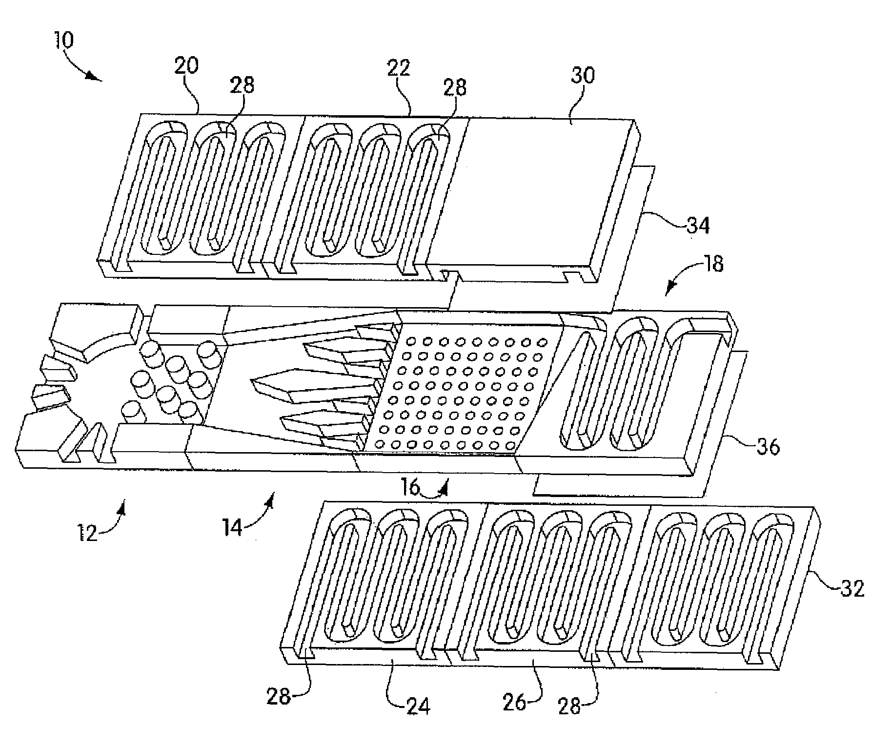
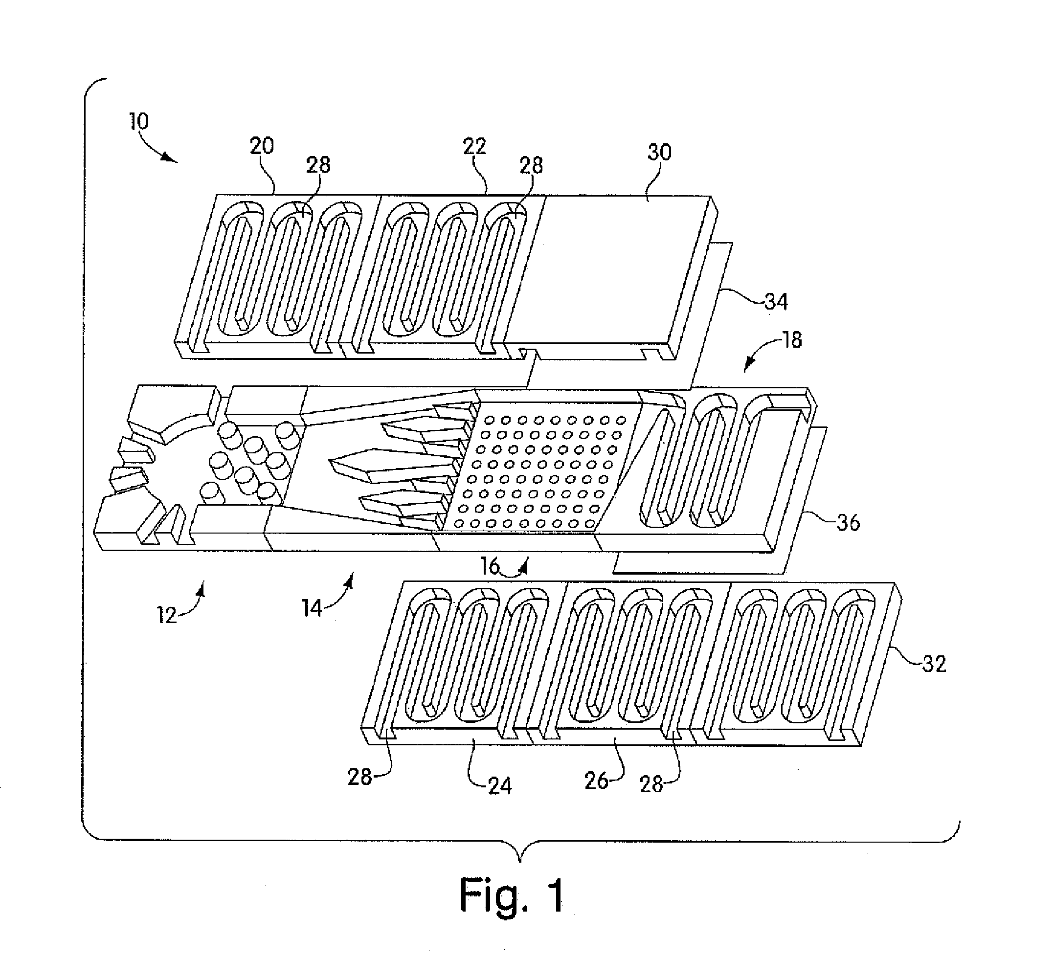
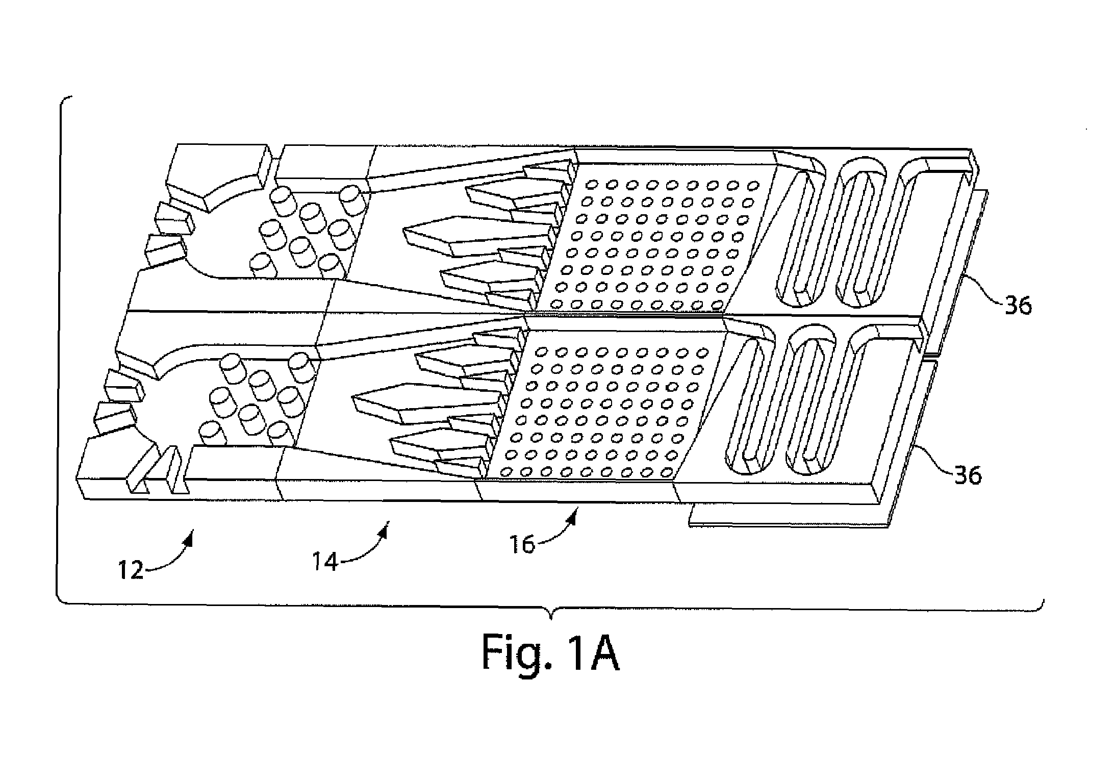
[0028]The present invention provides a chemical or biochemical reactor that can be used for a variety of very small-scale techniques. In one embodiment, a microreactor of the invention comprises a matrix of a few millimeters to a few centimeters in size containing reaction channels with dimensions on the order of hundreds of microns. Reagents of interest are allowed to flow through these microchannels, mixed, and reacted together. The products can be recovered, separated, and treated within the system. While one microreactor may be able only to hold and react a few microliters of the substances of interest, the technology allows for easy scalability and tremendous parallelization. With enhanced oxygen and nutrient distribution, a microreactor of the invention demonstrates increased performance in terms of cell viability. The microreactor geometry resembles closely the natural environment of cells whereby diffusional oxygen and nutrient transfer take place through a high surface area...


PUM

PropertyMeasurementUnit
Volumeaaaaaaaaaa
Temperatureaaaaaaaaaa

Abstract

Chemical and biological reactors, including microreactors, are provided. Exemplary reactors include a plurality of reactors operable in parallel, where each reactor has a small volume and, together, the reactors produce a large volume of product. Reaction systems can include mixing chambers, heating/dispersion units, reaction chambers, and separation units. Components of the reactors can be readily formed from a variety of materials. For example, they can be etched from silicon. Components are connectable to and separable from each other to form a variety of types of reactors, and the reactors can be attachable to and separable from each other to add significant flexibility in parallel and/or series reactor operation.

Description

RELATED APPLICATION[0001]This application claims the benefit of priority under 35 U.S.C. §119(e) of co-pending U.S. Provisional Patent Application Ser. No. 60 / 188,275, filed Mar. 10, 2000.FIELD OF THE INVENTION[0002]The present invention relates generally to chemical or biochemical microreactors, and more particularly to a microreactor for the production of the product of a chemical or biochemical reaction, including a plurality of individuated microreactors constructed to operate in parallel.BACKGROUND OF THE INVENTION[0003]A wide variety of reaction systems are known for the production of the product of chemical or biochemical reactions. Chemical plants involving catalysis, biochemical fermenters, pharmaceutical production plants, and a host of other systems are well-known.[0004]Systems for housing chemical and biochemical reactions not necessarily for the production of product also are known. For example, continuous-flow systems for the detection of various analytes in bodily flu...

Claims


Application Information

Patent Timeline
IPC IPC(8): C12M1/12G01N33/53B01F5/02B01F5/06B01F13/00B01J19/00B01J19/24B81B1/00B81B7/04C12M1/00C12M3/00C12P1/00C12P21/00G01N37/00
CPCB01F5/0256B01F5/061B01F5/0646B01F5/0647B01F13/0064B01F13/0094B01F15/00935B01J19/0093C12M23/16B01F2005/0621B01J2219/00783B01J2219/00828B01J2219/00835B01J2219/00862B01J2219/00871B01J2219/00873B01J2219/00889B01J2219/00907B01J2219/00957B01J2219/00961B01J2219/00963B01J2219/00966B01F25/23B01F25/4317B01F25/431B01F25/4331B01F25/433B01F33/3017B01F33/304B01F35/561
Inventor JURY, ANDREY ZARURANGELINO, MARK D.
Owner BIOPROCESSORS CORP
Why Eureka
Try Eureka