
Framework for hardware co-simulation by on-demand invocations from a block model diagram design environment

a block model diagram and design environment technology, applied in the field of hardware co-simulation frameworks, can solve the problems of not being able to describe dynamic system behavior, increasing time and effort involved in creating accurate, detailed models,

Active Publication Date: 2009-02-10
THE MATHWORKS INC
View PDF3 Cites 22 Cited by
  • Summary
  • Abstract
  • Description
  • Claims
  • Application Information

AI Technical Summary

Benefits of technology

[0015]The present invention relates to integration of a target processor into a simulation environment, such that the target processor operates in a processor in the loop (PIL) environment without the target platform being aware of the simulation environment. Unlike traditional static testing, wherein functionality of a particular component is tested by providing known inputs and measuring the outputs, dynamic testing such as PIL, using numerous input parameters, provides for testing of a design under real world conditions without the associated risks of actual real world testing. Furthermore, while using PIL, the performance of a simulated design can be evaluated using conditions that may seldom be encountered in the real world. For example, when using PIL of an automotive engine management controller, temperature extremes unlikely to be encountered in the real world may be evaluated, such that highly unlikely, yet possible, deficiencies in the controller can be determined. Furthermore, using PIL allows for rapid testing as the model may be run and tested at a speed faster than real time.
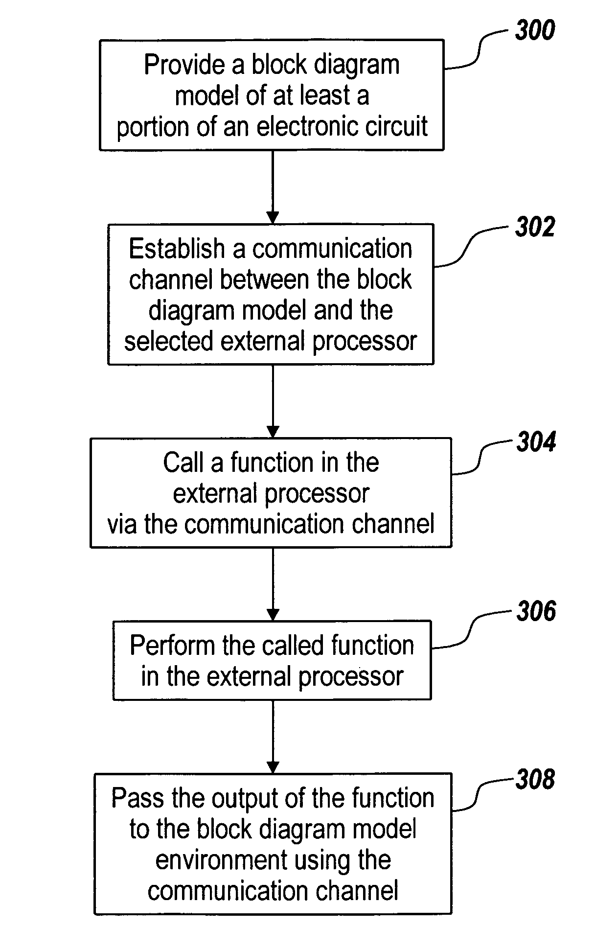
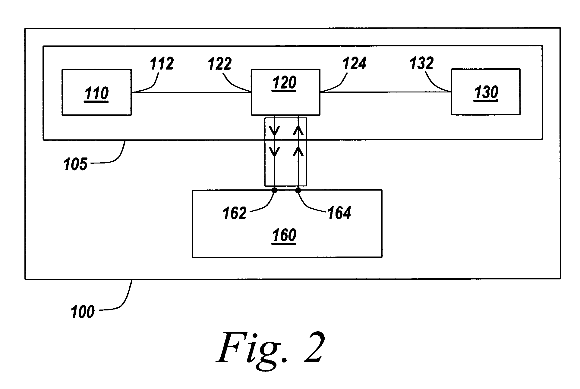
[0018]In accordance with another aspect, the present invention provides a system for simulating an electronic circuit, model or apparatus, wherein the system includes a simulation environment and a processor external thereto. The processor is located external to the simulation environment, such that the application executed by the external processor and the simulation environment run in different processes or threads, and potentially on different processors altogether, yet remain in communication with each other. Furthermore, the simulation environment can call a function for execution on the processor via the communication channel, from within the simulation model. The call of a function for execution on the external processor is such that the output of the called function in the external processor can be retrieved by the simulation environment and further used within the simulation environment without the use of specific drivers for passing data.

Problems solved by technology

Such systems range from simple to highly complex systems.
Flow-charts are used to capture process flow and are not generally suitable for describing dynamic system behavior.
As systems become more complex, an increasingly large amount of time and effort is involved in creating accurate, detailed models.
However, testing of this deployed version of code in a co-simulation environment is difficult or impossible, therefore there exists a great potential for code conflicts and unanticipated negative results in the deployed version of the code.

Method used


Image

  • Framework for hardware co-simulation by on-demand invocations from a block model diagram design environment
  • Framework for hardware co-simulation by on-demand invocations from a block model diagram design environment
  • Framework for hardware co-simulation by on-demand invocations from a block model diagram design environment

Examples


Embodiment Construction

[0030]The present invention relates to integration of a target processor into a simulation environment, such that the target processor operates in a processor in the loop (PIL) environment without the target platform being aware of the simulation environment. Unlike traditional static testing, wherein functionality of a particular component is tested by providing known inputs and measuring the outputs, dynamic testing such as PIL, using numerous input parameters, provides for testing of a design under real world conditions without the associated risks of actual real world testing. Furthermore, while using PIL, the performance of a simulated design can be evaluated using conditions that may seldom be encountered in the real world. For example, when using PIL of an automotive engine management controller, temperature extremes unlikely to be encountered in the real world may be evaluated, such that highly unlikely, yet possible, deficiencies in the controller can be determined. Further...


PUM


Abstract

The present invention relates to integration of an external processor capable of execution of one or more functions into a block diagram model environment such that the block diagram model environment can make function calls directly into the external processor without the need for traditional wait loops or handshaking means. Furthermore the results of the function that was called in the external processor can be passed to the block diagram model environment from the external processor.

Description

RELATED APPLICATIONS[0001]The present application claims priority to U.S. Provisional Application Ser. No. 60 / 611,617 filed Sep. 20, 2004 for all subject matter common to both applications. The disclosure of the above-mentioned application is hereby incorporated by reference herein in their entirety.FIELD OF THE INVENTION[0002]The present invention relates to integration of target platform code into the context of a simulation, in particular to methods and systems for providing a scalable code implementation solution wherein the target is unaware of the simulation and a function performed by the target is invoked by the host from the simulation.BACKGROUND OF THE INVENTION[0003]Block diagrams are used to model real-world systems. Historically, engineers and scientists have utilized time-based block diagram models in numerous scientific areas such as Feedback Control Theory and Signal Processing to study, design, debug, and refine dynamic systems. Dynamic systems, which are characteri...

Claims


Application Information

Patent Timeline
IPC IPC(8): G06F9/45
CPCG06F17/5009G06F9/4411G06F2217/74G06F2111/12G06F30/20
Inventor KOH, DAVIDNAZARIO, MARY ANNOROFINO, II, DONALD PAUL
Owner THE MATHWORKS INC
Learn More