Exhaust gas recirculation and selective catalytic reduction system

a catalytic reduction and exhaust gas technology, applied in the direction of non-fuel substance addition to fuel, mechanical equipment, machines/engines, etc., can solve the problems of hazardous storage of ammonia, high cost of ammonia on board production, and specialized equipment, so as to facilitate the reaction and facilitate the reaction

Inactive Publication Date: 2009-02-17
CATERPILLAR INC
View PDF26 Cites 32 Cited by
  • Summary
  • Abstract
  • Description
  • Claims
  • Application Information

AI Technical Summary

Problems solved by technology

However, because of the high reactivity of ammonia, storage of ammonia can be hazardous.
Further, on-board production of ammonia can be costly and may require specialized equipment.
In particular, some engines may operate under conditions whereby an EGR system may not provide sufficient emission reduction.
However, the engine of the '489 patent includes only an EGR system and is not configured to operate with an SCR system that may further reduce emissions.

Method used


Image

  • Exhaust gas recirculation and selective catalytic reduction system
  • Exhaust gas recirculation and selective catalytic reduction system
  • Exhaust gas recirculation and selective catalytic reduction system

Examples


Embodiment Construction

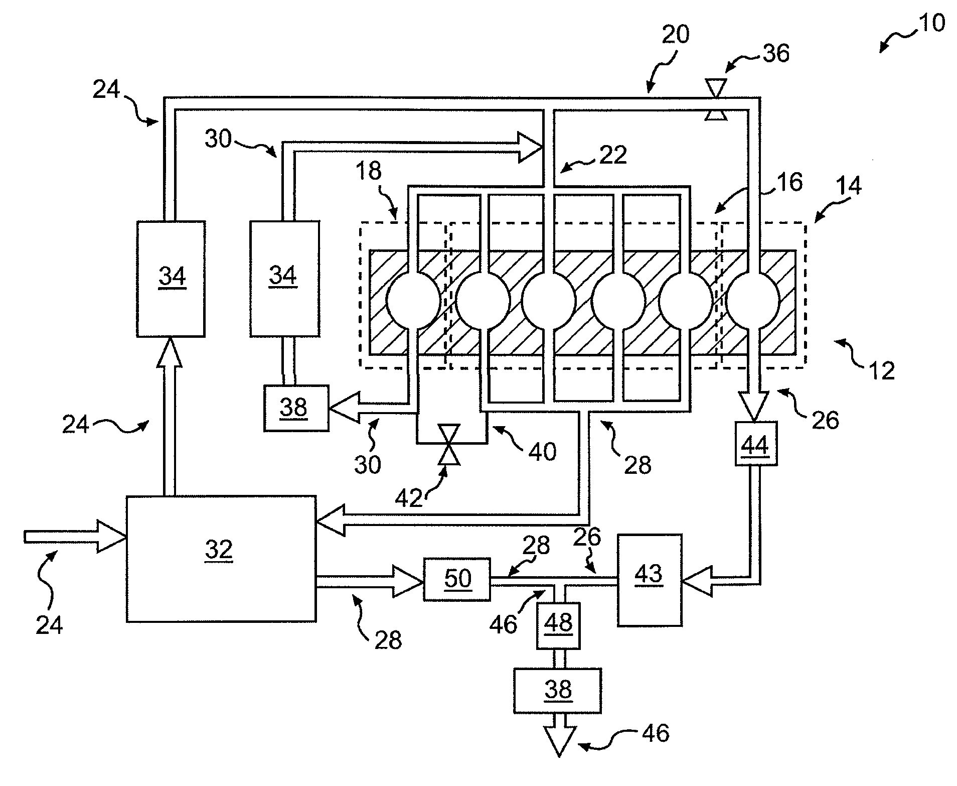
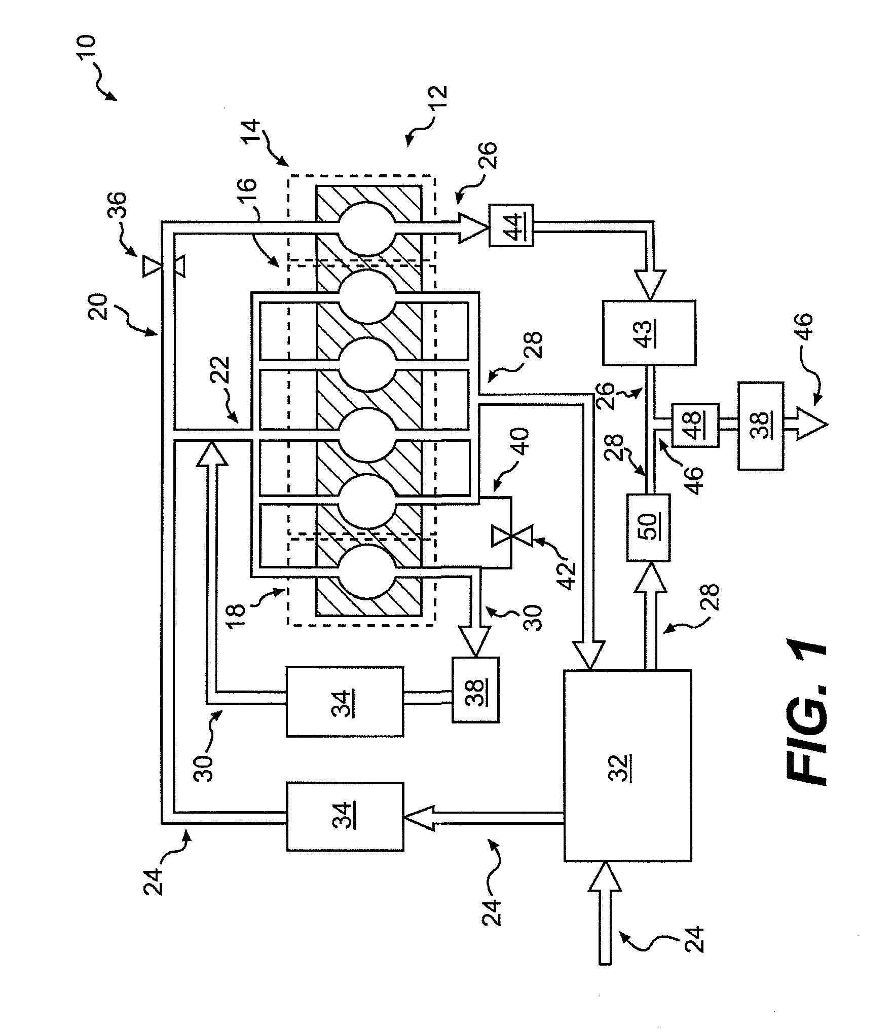
[0014]FIG. 1 provides a schematic representation of a machine 10 of the present disclosure including a power source 12. In some embodiments, power source 12 may include any type of internal combustion engine. For example, power source 12 may include a diesel engine, a gasoline engine, a gaseous fuel-powered engine, or any other engine known in the art. Further, power source 12 may be configured to provide power to an on-highway vehicle, construction or mining equipment, or a factory or power plant.

[0015]Power source 12 may include a plurality of cylinders, including a first cylinder group 14, a second cylinder group 16, and a third cylinder group 18. Each of cylinder groups 14, 16, 18 may include one or more cylinders configured to permit fuel combustion in addition, each cylinder group may be configured to operate at different-operating conditions. For example, one cylinder group may be operated to provide power, another cylinder group may be operated to recirculate at least a port...


PUM


Abstract

A power source is provided for use with an exhaust gas recirculation and selective catalytic reduction system. The power source has a main air-intake passage fluidly connected to a first air-intake passage and a second air-intake passage. A first cylinder group may be fluidly connected to the first air-intake passage and a first exhaust passage, wherein the first exhaust passage may include an ammonia-producing catalyst configured to convert at least a portion of a fluid in the first exhaust passage into ammonia. Further, a second cylinder group may be fluidly connected to the second air-intake passage and a second exhaust passage. A third cylinder group may be fluidly connected to the second air-intake passage. The power source may have a recirculation loop that includes the second air-intake passage and the third cylinder group. The power source may also have a merged exhaust passage configured to connect the first exhaust passage and the second exhaust passage to facilitate a reaction between ammonia and NOx to at least partially remove NOx from the merged exhaust passage.

Description

TECHNICAL FIELD[0001]This disclosure relates generally to an exhaust gas recirculation and selective catalytic reduction system, and more particularly, to a high pressure exhaust gas recirculation system with on-board ammonia production.BACKGROUND[0002]Engines, including diesel engines, gasoline engines, gaseous fuel-driven engines, and other engines known in the art, traditionally exhaust a complex mixture of pollutants. These emissions may include gaseous and solid material, such as, particulate matter, nitrogen oxides (NOx), and sulfur compounds. Heightened environmental concerns have led regulatory agencies to increase the stringency of emission standards for such engines, forcing engine manufactures to develop systems to further reduce levels of engine emissions.[0003]One method used by engine manufacturers to reduce engine emissions includes exhaust gas recirculation (EGR). EGR systems recirculate a portion of the engine exhaust stream into the air-intake supply of the engine ...

Claims


Application Information

Patent Timeline
Patent Type & Authority Patents(United States)
IPC IPC(8): F01N3/10
CPCF01N3/035F01N3/2066F02M25/0742F01N13/009F01N13/011F01N2240/25F01N2610/02F02B29/0412F02B29/0425F02B29/0437F02B37/00F02M25/074Y02T10/121Y02T10/24F02M26/35F02M26/36Y02T10/12
Inventor ROBEL, WADE J.BAILEY, BRETT M.
Owner CATERPILLAR INC
Why Eureka
Try Eureka