
Multi-band cellular antenna

Inactive Publication Date: 2009-03-03
AGC AUTOMOTIVE AMERICAS
View PDF20 Cites 25 Cited by
  • Summary
  • Abstract
  • Description
  • Claims
  • Application Information

AI Technical Summary

Benefits of technology

[0010]The antenna of the subject invention provides excellent performance characteristics when transmitting and / or receiving RF signals in the first and second cellular frequency bands. These characteristics include high radiation gain, high radiation efficiency, and wider bandwidths at the first and second frequency bands. Because the antenna of the subject invention is integrated with the window, the antenna is generally conformal with the window and is relatively compact, occupying a relatively small area of the window, yet still providing a high performance when transmitting or receiving cellular RF signals. Further, the layout and compact size of the antenna make it non-obtrusive to the driver's visibility and therefore minimizes aesthetic and safety obstructions. Therefore, the antenna of the subject invention is desirable for automotive manufacturers and drivers of the vehicles.

Problems solved by technology

The characteristics of glass such as automotive glass, and the angled disposition of this glass when applied as a window of a vehicle, provide challenges to the effective integration of an antenna with the window of the vehicle.
However, this placement limits the placement flexibility and potentially the performance of the antenna.
Notably, because the antenna of the '819 patent has antenna elements disposed on both sides of the dielectric, there are manufacturing challenges when integrating such a design on automotive glass such as tempered glass.
Additionally, the antenna of the '819 patent has a larger footprint than desired by the automotive manufacturers to be integrated with automotive glass.
Additionally, there remains an opportunity for a high-performing antenna that, when integrated with an automotive window, does not create a substantial visual obstruction nor alter the aesthetic appearance of the vehicle yet still maintains optimal reception.

Method used


Image

  • Multi-band cellular antenna
  • Multi-band cellular antenna
  • Multi-band cellular antenna

Examples


Embodiment Construction

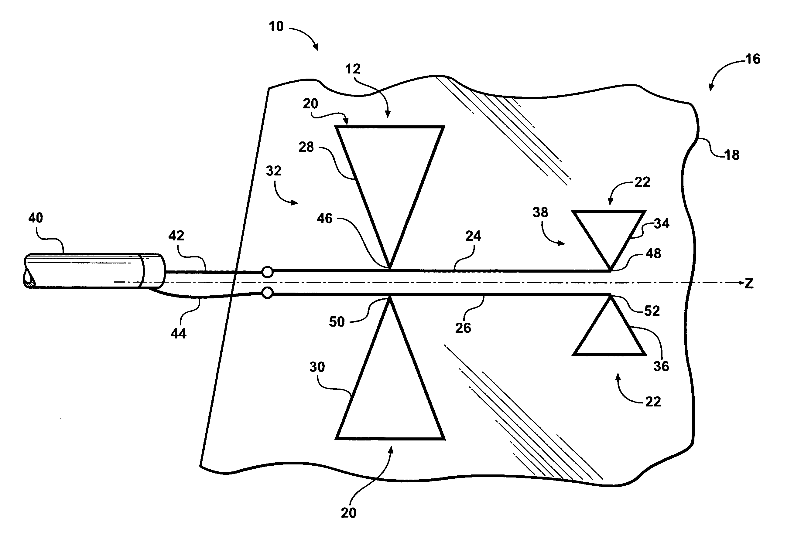
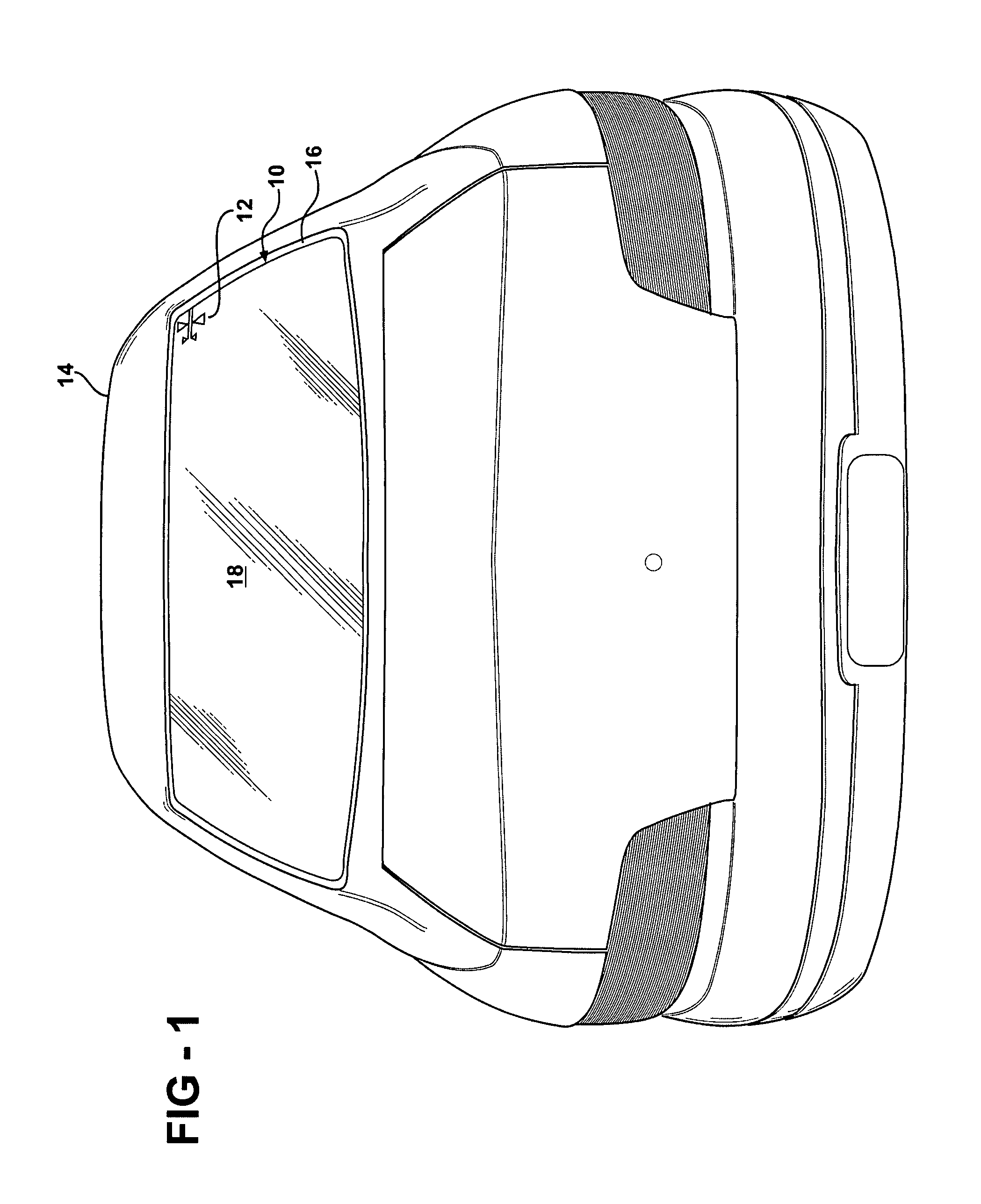
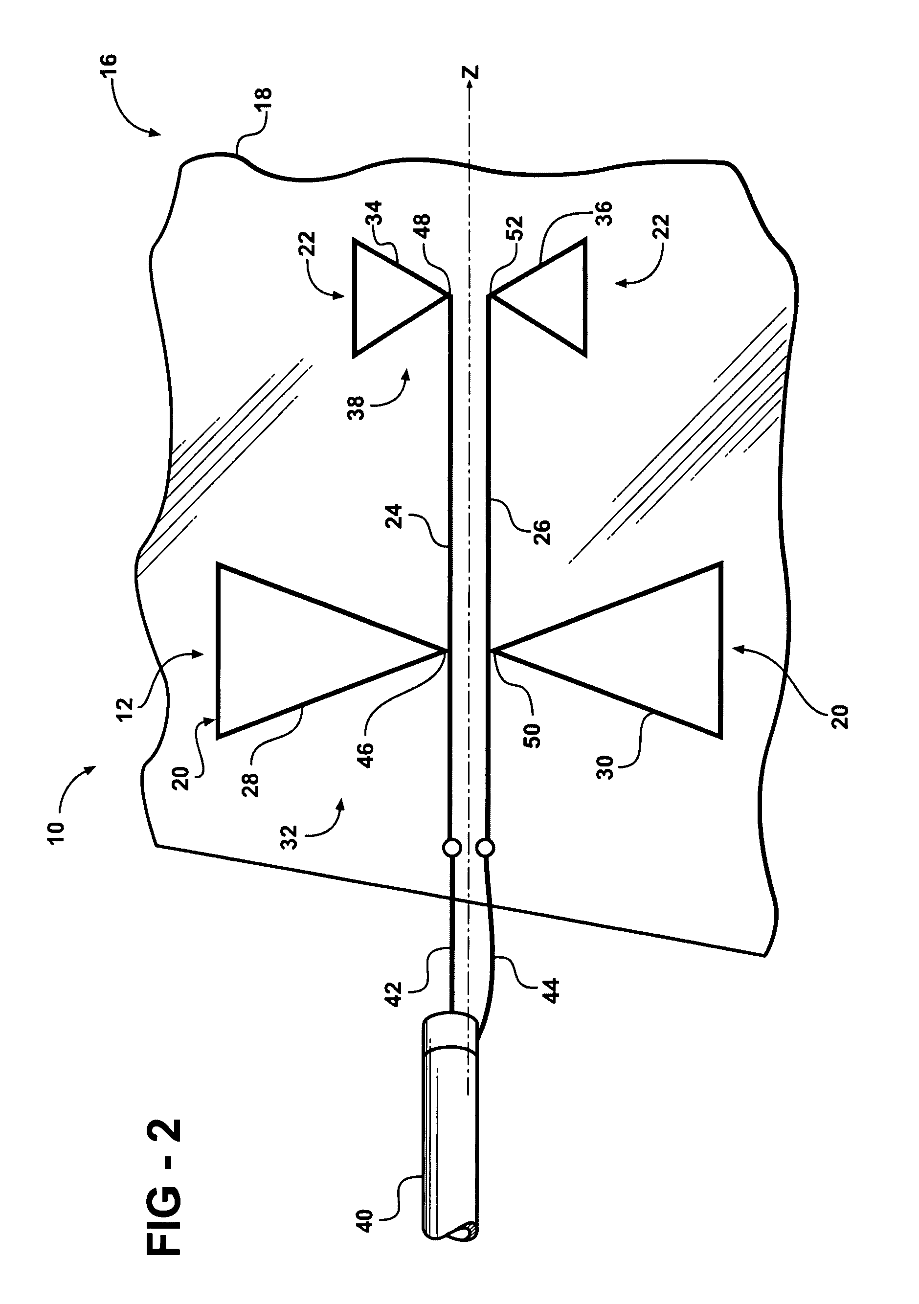
[0020]Referring to the Figures, wherein like numerals indicate like parts throughout the several views, a window 10 having an integrated antenna 12 for dual band operation at a first frequency band and a second frequency band is generally shown. This window 10 may be a rear window (backlite) as shown in FIG. 1, a front window (windshield), or any other window of a vehicle 14. The integrated antenna 12, hereinafter simply referred to as the antenna 12, may also be implemented in other situations completely separate from the vehicle 14, such as on a building or integrated with a radio transceiver, as long as the transceiver includes a non-conductive pane 16.

[0021]The window 10 includes the non-conductive pane 16. The term “nonconductive” refers to a material, such as an insulator or dielectric, that when placed between conductors of different potentials, permits only a small or negligible current in phase with the applied voltage to flow through material. Typically, nonconductive mate...


PUM


Abstract

An antenna for receiving and / or transmitting radio frequency (RF) signals at multiple cellular frequency bands is disposed on a non-conductive pane. The antenna includes a first antenna element and a second antenna element. The first antenna element has a first radiating element and a second radiating element arranged together in an opposing relationship to form a first bowtie shape. The second antenna element is spaced from the first antenna element and has a third radiating element and a fourth radiating element arranged together in an opposing relationship to form a second bowtie shape with a different dimension than the first bowtie shape. A first trace element connects to and extends between said first and third radiating elements and a second trace element connects to and extends between said second and fourth radiating elements. The antenna establishes an electromagnetic coupling for dual band operation at the multiple cellular frequency bands.

Description

FIELD OF THE INVENTION[0001]The subject invention generally relates to an antenna for receiving and / or transmitting radio frequency (RF) signals at multiple cellular frequency bands.BACKGROUND OF THE INVENTION[0002]Vehicles have long implemented glass to enclose a cabin of the vehicle while still allowing visibility for the driver of the vehicle. The glass is typically disposed on an angle to enclose the cabin. Automotive glass is typically either a tempered (or toughened) glass or a laminated glass which is produced by bonding two or more panes of glass together with a plastic interlayer. The characteristics of glass such as automotive glass, and the angled disposition of this glass when applied as a window of a vehicle, provide challenges to the effective integration of an antenna with the window of the vehicle. Automotive manufacturers have strict requirements as to the amount of visual obstruction caused by antennas integrated with windows of the vehicle. As is known in the art,...

Claims


Application Information

Patent Timeline
IPC IPC(8): H01Q1/32
CPCH01Q1/1271H01Q9/285H01Q21/30
Inventor LEE, KWAN-HOVILLARROEL, WLADIMIROSURITTIKUL, NUTTAWITGEDDE, JESUS
Owner AGC AUTOMOTIVE AMERICAS
Learn More