Hydraulic driving system of construction machinery

a technology of hydraulic drive system and construction machinery, which is applied in the direction of positive displacement liquid engine, fluid coupling, servomotor, etc., can solve the problems of large pressure loss in the whole of the hydraulic circuit, large pressure loss in the hoses, and restricted allowable capacity of the main line, so as to ensure smooth and reliable valve opening/closing operation

Active Publication Date: 2009-03-10
NIHON KENKI CO LTD
View PDF8 Cites 17 Cited by
  • Summary
  • Abstract
  • Description
  • Claims
  • Application Information

AI Technical Summary

Benefits of technology

[0011]In general, a hydraulic cylinder has a large volume difference (e.g., about 2:1) between a rod pushing-side chamber and a rod drawing-side chamber thereof. Accordingly, when constructing an actual super-large-sized hydraulic excavator, components to be essentially added for supply of the hydraulic fluid at the above-described large flow rate are only six in total, i.e., the boom bottom-side inflow control valve, the arm bottom-side inflow control valve and the bucket bottom-side inflow control valve for supplying the hydraulic fluid to the respective pushing-side chambers, and the boom bottom-side outflow control valve, the arm bottom-side outflow control valve and the bucket bottom-side outflow control valve for draining the return hydraulic fluid from the respective rod pushing-side chambers. The six flow control valves connected to the respective rod drawing-side chambers are not always required from the practical point of view. If those six flow control valves connected to the respective rod drawing-side chambers can be omitted, it should be possible to reduce the pressure loss caused by those six directional flow control valves themselves. Also, it should be possible to omit piping associated with those directional flow control valves and hence cut the pressure loss otherwise caused by such piping, and to realize a further reduction of the total pressure loss. In addition, a reduction in the number of hydraulic units, such as the directional flow control valves, could simplify layouts including routing of various pipes and arrangements of various units, particularly layouts of hydraulic piping between the hydraulic pumps as hydraulic sources and actuators receiving the hydraulic fluids from the hydraulic sources.
[0045]With that feature, in operation, the front operating mechanism rotates in the direction perpendicular to the axis of the seat valve. Therefore, the rotating operation of the front operating mechanism is avoided from adversely affecting the opening / closing operation of the seat valve, and smooth and reliable valve opening / closing operation can be ensured.

Problems solved by technology

Accordingly, an allowable capacity as the main lines is restricted as compared with the supply and drain flow rate required for a hydraulic actuator, and a relatively large pressure loss occurs in each of hoses constituting the main lines.
Hence, a very large pressure loss is eventually generated in the whole of a hydraulic circuit of the super-large-sized machine having long lines formed of hoses, steel piles or the likes, flow control selector valves, etc.
The pressure loss increases an energy loss and causes another problem that the operating speed of the hydraulic actuator reduces and the working efficiency deteriorates.

Method used


Image

  • Hydraulic driving system of construction machinery
  • Hydraulic driving system of construction machinery
  • Hydraulic driving system of construction machinery

Examples


first embodiment

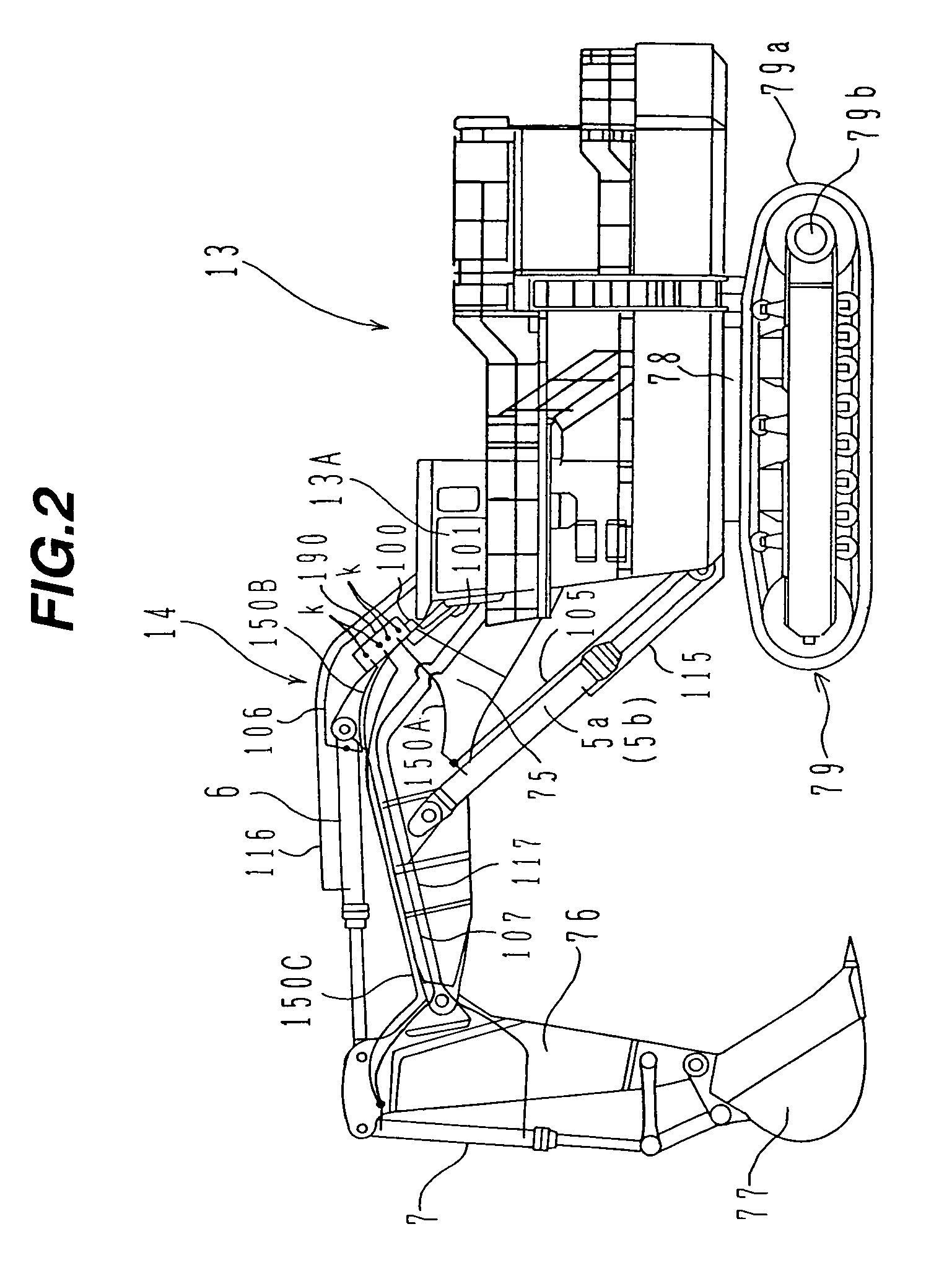
[0062]the present invention will be described with reference to FIGS. 1 to 3. This embodiment represents the case in which the present invention is applied to the so-called super-large-sized backhoe type hydraulic excavator of a class having its own weight of 70 tons, for example.

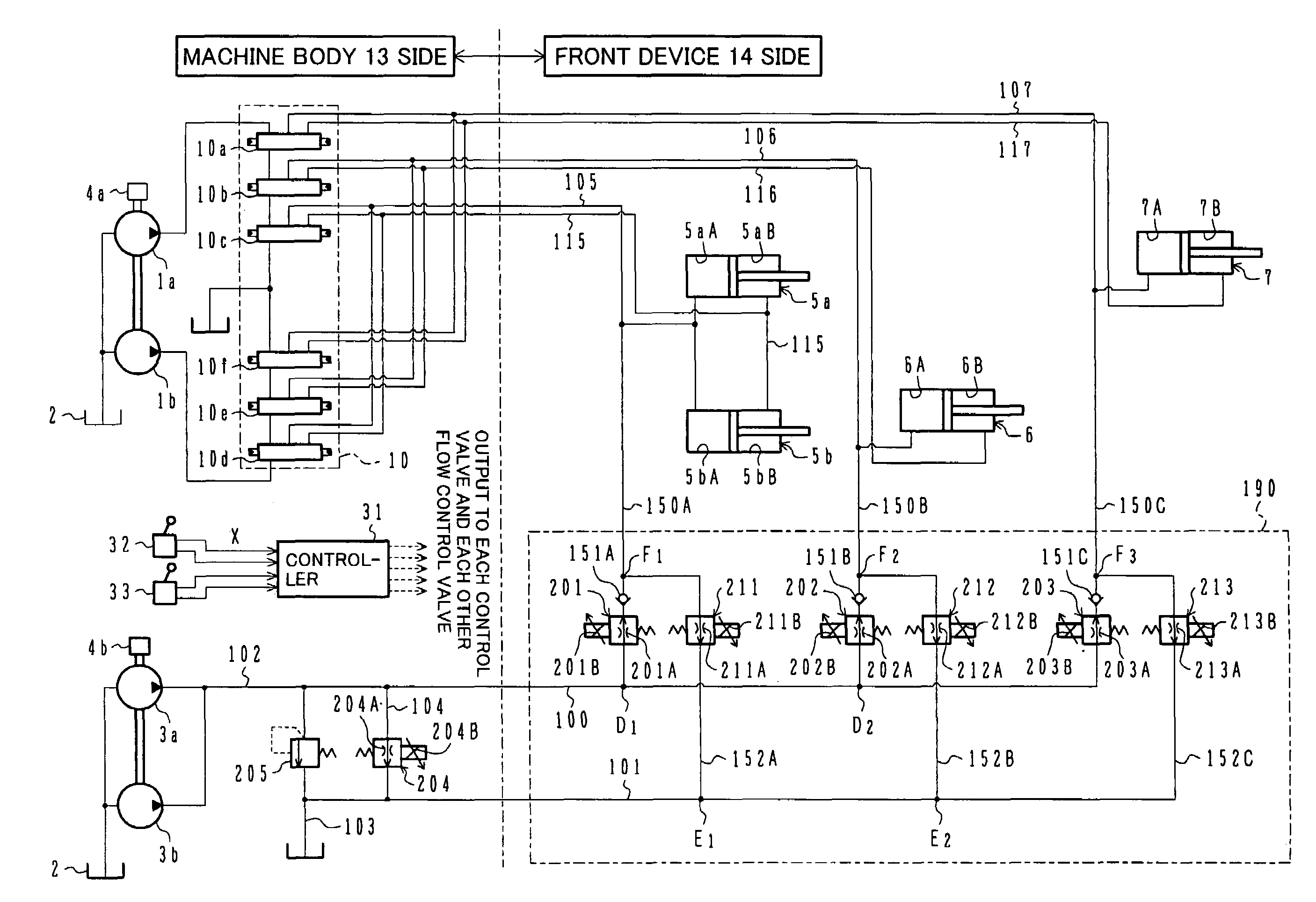
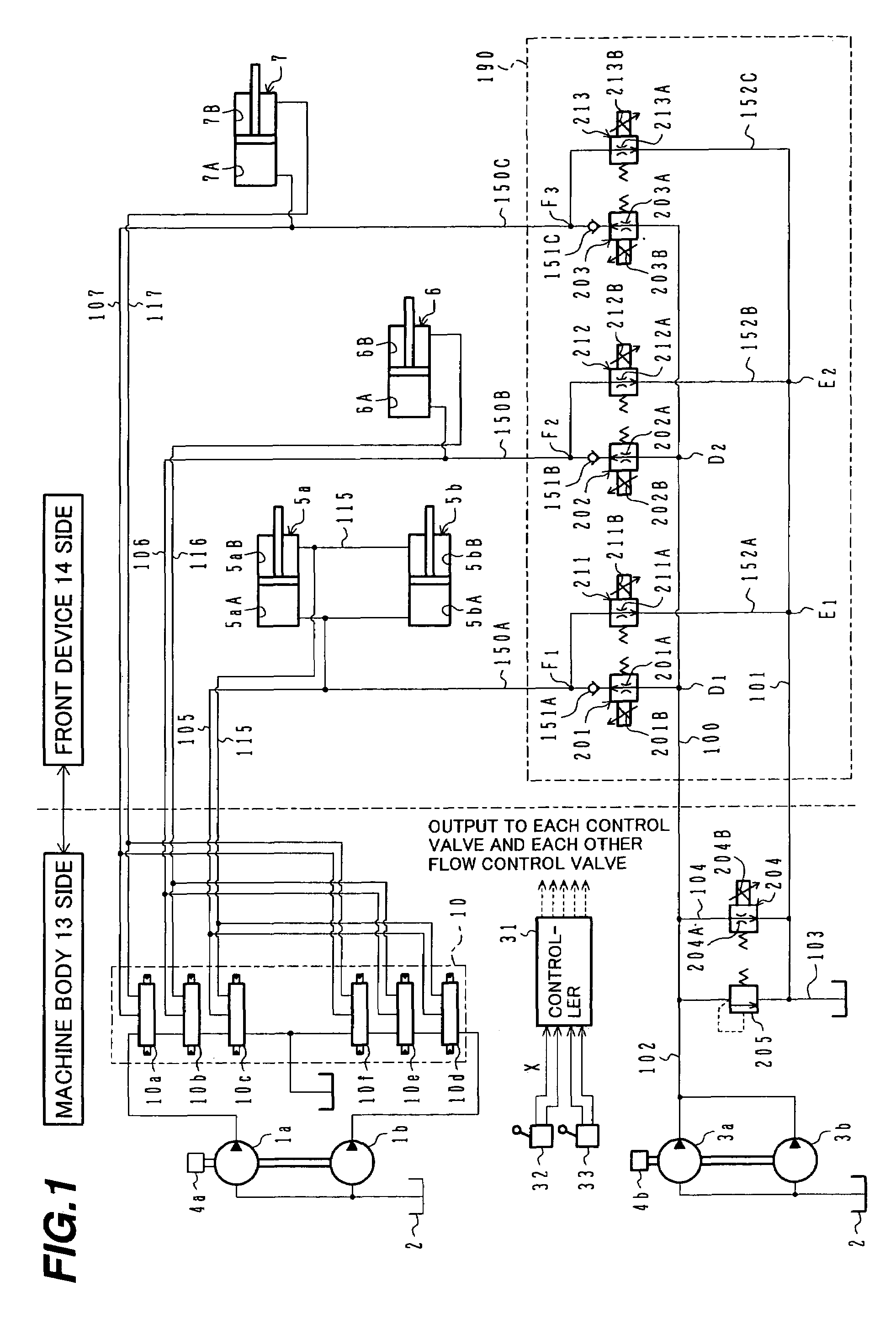
[0063]FIG. 1 is a hydraulic circuit diagram showing the overall construction of a hydraulic drive system according to this embodiment along with a control system for it. Referring to FIG. 1, the hydraulic drive system of this embodiment comprises hydraulic pumps 1a, 1b driven by an engine (prime mover) 4a, hydraulic pumps 3a, 3b driven by an engine 4b (allocation of the hydraulic pumps 1a, 1b, 3a and 3b with respect to the engines 4a, 4b is not limited to the above-described one, and may be set as appropriate in consideration of horsepower distribution, etc.), boom hydraulic cylinders 5a, 5b, an arm hydraulic cylinder 6 and a bucket hydraulic cylinder 7 which are supplied with hydraulic fluids delivered fro...

third embodiment

[0136]the present invention will be described with reference to FIG. 7.

[0137]FIG. 7 is a hydraulic circuit diagram showing a principal part of the construction of a hydraulic drive system according to this embodiment. Identical components to those in the first and second embodiments are denoted by the same symbols, and a description of those components is omitted here as appropriate.

[0138]In the first and second embodiments, taking into account that the rod pushing-side chambers 5aA, 5bA of the boom hydraulic cylinders, the rod pushing-side chamber 6A of the arm hydraulic cylinder, and the rod pushing-side chamber 7A of the bucket hydraulic cylinder have relatively large volume ratios, the boom inflow control valve 201, the arm inflow control valve 202, and the bucket inflow control valve 203 are provided to control the supply of the hydraulic fluids from the hydraulic pumps 3a, 3b to the rod pushing-side chambers 5aA, 5bA, 6A and 7A, and the boom outflow control valve 211, the arm ...

fourth embodiment

[0141]the present invention will be described with reference to FIG. 8.

[0142]FIG. 8 is a hydraulic circuit diagram showing a principal part of the construction of a hydraulic drive system according to this embodiment. Identical components to those in the first to third embodiments are denoted by the same symbols, and a description of those components is omitted here as appropriate.

[0143]In contrast with the above third embodiment, when only the draining of the hydraulic fluids from the rod pushing-side chambers 5aA, 5bA, 6A and 7A is required to be taken into consideration, it is sufficient to provide only the outflow control valves 211, 212 and 213 with omission of the inflow control valves 201, 202 and 203, etc., the hydraulic pumps 3a, 3b, the prime mover 4b, the lines 102, 100 and 104, respective portions of the lines 150A, 150B and 150C in which the inflow control valves 201, 202 and 203 are disposed, the bypass flow control valve 204, the relief valve 205, etc., which are used...


PUM


Abstract

A hydraulic drive system comprises directional flow control valves (10a-f) for selectively supplying a hydraulic fluid from a first hydraulic pump (1a, 1b), inflow control valves (201-203) disposed respectively in branch lines (150A-C) branched from a supply line (100) for supplying a hydraulic fluid delivered from a second hydraulic pump (3a, 3b) to rod pushing-side chambers (5aA, 5bA, 6A, 7A) of hydraulic cylinders, a bypass flow control valve (204) disposed in a line (104) connecting the supply line (100) and a reservoir (2), and a controller (31) for computing control variables corresponding to operation command signals from control levers (32, 33) and controlling the inflow control valves (201-203) and the bypass flow control valve (204) in accordance with the computed control variables. Thus, the number of flow control valves and the length of piping required for their connection can be reduced, and a total pressure loss can be further reduced.

Description

TECHNICAL FIELD[0001]The present invention relates to a hydraulic drive system for a construction machine such as a hydraulic excavator, and more particularly to a hydraulic drive system for a construction machine, which is suitably used in the so-called super-large-sized hydraulic excavator.BACKGROUND ART[0002]As disclosed in FIG. 9 of JP,A 9-328784, for example, there is conventionally known a hydraulic drive system for a construction machine, which is applied to a construction machine such as a super-large-sized hydraulic excavator of a class having its own weight of 70 tons or more, in particular, the so-called backhoe type hydraulic excavator including a swing body swingably mounted on a lower travel structure and a multi-articulated front operating mechanism comprising a boom rotatably coupled to the swing body, an arm rotatably coupled to the boom, and a bucket rotatably coupled to the arm to be open rearward in a ground contact state.[0003]Such a hydraulic drive system compr...

Claims


Application Information

Patent Timeline
Patent Type & Authority Patents(United States)
IPC IPC(8): E02F9/00E02F9/20F15B11/00E02F9/22F15B11/16F15B11/17F15B21/08
CPCE02F9/2228E02F9/2242E02F9/2292F15B11/165F15B11/167F15B11/17F15B21/087F15B2211/20576F15B2211/30505F15B2211/3056F15B2211/3116F15B2211/31576F15B2211/327F15B2211/40515F15B2211/40546F15B2211/413F15B2211/4159F15B2211/426F15B2211/45F15B2211/476F15B2211/50518F15B2211/665F15B2211/71E02F9/20
Inventor UDAGAWA, TSUTOMUTAKIGUCHI, KAZUOOCHIAI, MASAMIYAGYUU, TAKASHISUGIYAMA, YUKIHIKOAIHARA, MITSUO
Owner NIHON KENKI CO LTD
Why Eureka
Try Eureka