Rotary valve and analytical chromatographic system using the same

a technology of chromatographic system and rotary valve, which is applied in the direction of multiple way valve, component separation, instruments, etc., can solve the problems of high cost, high cost, and high difficulty in achieving good sealing, so as to eliminate the build up and the possibility

Active Publication Date: 2009-03-17
APN INC
View PDF26 Cites 57 Cited by
  • Summary
  • Abstract
  • Description
  • Claims
  • Application Information

AI Technical Summary

Benefits of technology

[0025]In another preferred embodiment of the present invention, the inner recess has an annular portion defining a central rotor interface portion therein. The ports are particularly arranged so that at anyone of the rotor positions one of the ports is aligned with one of the rotor interface portions. The fluid channel has first and second openings extending in the rotor interface. The first opening extends in the central rotor interface portion and provides a continuous fluid communication with a corresponding port aligned therewith. The second opening extends in one of the remaining rotor interface portions and provides a fluid communication with a corresponding port aligned therewith for a given rotor position, thereby providing a fluid flow path between the two ports in simultaneous fluid communication with the first and second openings.
[0028]Advantageously, the rotary valve of the present invention prevents cross-port leaks and allows to cancel the effect of any possible leaks by evacuating them. Furthermore, the sweeping action of the rotor's separation recesses and the corresponding flowing fluid advantageously eliminate the build up and the possibilities of particles trapping that will otherwise dramatically damage the rotor and stator surface. The sweeping fluid in the rotor's separation recesses advantageously provide a self cleaning action. The present rotary valve also presents an improved lifetime.

Problems solved by technology

In this case, if the sample background reaches the detector, a huge peak will result, masking some of the impurities of interest, and some types of detectors could be damaged by overloading.
Molecule sizes are much bigger and their shapes much more complex for liquids than gases.
However, when the carrier or sample is H2 or He, a good sealing is extremely difficult to achieve.
The smallest scratch on the stator or rotor surface resulting from surface finish imperfection will cause leaks from port to port.
This makes it difficult to get good sealing for long periods of time.
Equipment downtime is undesirable.
However, for process chromatograph, frequent downtime is a serious problem.
When a valve slowly begins to leak, the analytical results become unstable and inaccurate.
All of them suffer from fast wearing caused by particle contamination, or simply by the friction between the various planar surfaces.
There are no means to prevent or delay cross-port flow contamination over the time.
However, this type of seal requires frequent replacement.
Sealing effect relies on constant pressure applied by both planar surfaces on the seal, particle contamination causes seal wearing and leaks occur.
Furthermore, no means are provided to avoid cross-port leaks when the surface becomes scratched by the fluid's particle or by particles coming from the seal wearing.
There is an evacuation groove in the rotor that will carry away the leak coming from unselected channels, however there are serious drawbacks.
This method does not fix the problem of cross-port leak between unselected ports.
There is also a dead volume in the rotor.
There is also an O-ring between the rotor and valve housing acting as a seal, so out-gassing could occur and O-ring wearing will cause leak.
However, there is also a serious drawback since the system uses O-ring for sealing.
So, out-gassing will occur as well as leaks because of wearing.
Leaking will therefore occur and maintenance will be required.

Method used


Image

  • Rotary valve and analytical chromatographic system using the same
  • Rotary valve and analytical chromatographic system using the same
  • Rotary valve and analytical chromatographic system using the same

Examples


Embodiment Construction

[0061]In the following description, similar features in the drawings have been given similar reference numerals and in order to weight down the figures, some elements are not referred to in some figures if they were already identified in a precedent figure.

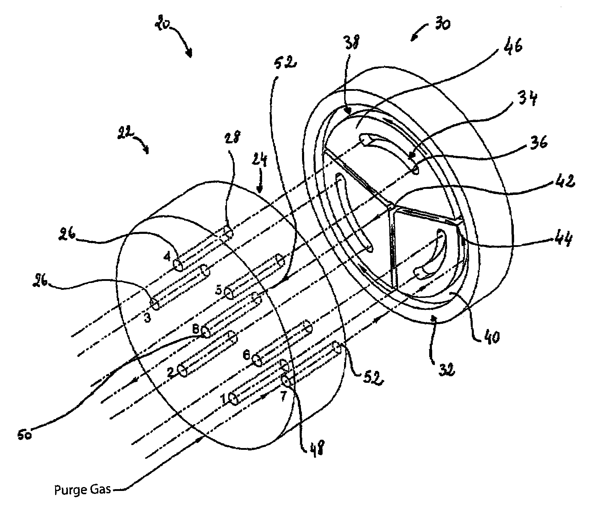
[0062]The present invention relates to a rotary valve for injecting sample fluid into a flowing fluid or to individually select process fluids from a plurality of process sample points. It could also be used for multi-function fluid and flow path for gas chromatography. Thus, the present invention provides a multi-port and a multi-positions rotary valve and a method that can be used for sample stream selections, sample injection or multi-function valves used in analytical systems or in industrial application like hydraulic and pneumatic systems. It should be understood that throughout the present description, the expression “fluid” is intended to cover any fluid such as gas or liquid. In other words, the rotary valve of the presen...


PUM

PropertyMeasurementUnit
pressureaaaaaaaaaa
temperatureaaaaaaaaaa
timeaaaaaaaaaa

Abstract

There is provided a rotary valve for fluid analytical systems. The present valve provides improved characteristics such as an extended lifetime. The valve can fulfil different fluid analytical functions and can be a multi-ports and / or multi-positions valve. The valve is provided with extra recesses in the rotor and extra ports in the stator. These recesses allow to cancel the effect of any possible leaks by evacuating them. Such a valve then prevents cross-port leaks and can advantageously be used in highly critical applications. Moreover, the present valve can be used in an analytical system which is advantageously self-diagnostic.

Description

FIELD OF THE INVENTION[0001]The present invention generally relates to a rotary valve for fluid analytical systems, and more particularly concerns a rotary valve having improved characteristics. The present invention also concerns an analytical chromatographic system using such a rotary valve.BACKGROUND OF THE INVENTION[0002]In various analytical methods, i.e. chromatography, online measurement and others, many scientific instruments need fluid controlling device. Most of the time, this is achieved by using different types of fluid flow path switching valves. As non-limitative examples, the function of these valves could be for sample injection, sample stream selection, fluid redirection, fraction collection, solvent selection, separation column selection or combination and other fluid switching flow paths required to realize a particular analytical method.[0003]In these systems, the fluid pressure range could be from vacuum to value in the neighbourhood of 10,000 psig. The fluid ph...

Claims


Application Information

Patent Timeline
Patent Type & Authority Patents(United States)
IPC IPC(8): G01N30/04
CPCF16K11/074G01N30/20G01N35/1097G01N2030/202Y10T137/1044Y10T137/1116Y10T137/86863
Inventor GAMACHE, YVESFORTIER, ANDRE
Owner APN INC
Why Eureka
Try Eureka