Microstructured transmission optical fiber

a transmission optical fiber and microstructure technology, applied in the field of optical fibers, to achieve the effect of improving bend resistan

Inactive Publication Date: 2009-03-17
CORNING INC
View PDF28 Cites 66 Cited by
  • Summary
  • Abstract
  • Description
  • Claims
  • Application Information

AI Technical Summary

Benefits of technology

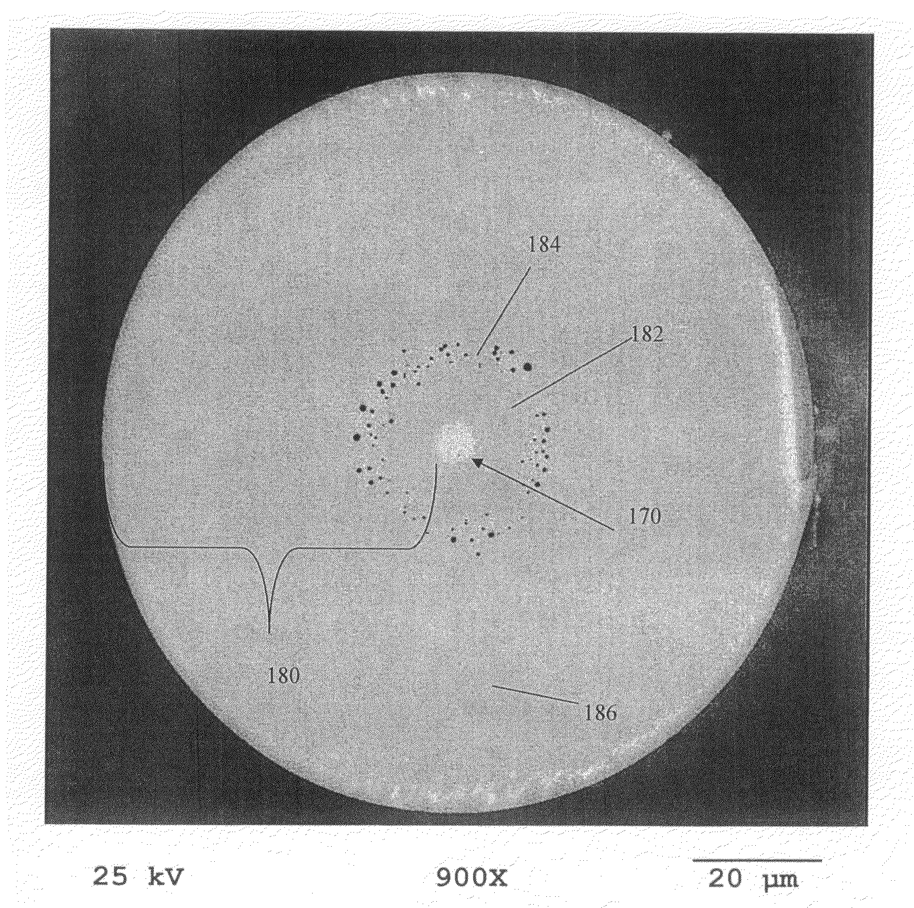
[0008]Microstructured optical fibers are disclosed herein comprising a core region and a cladding region surrounding the core region, the cladding region comprising an annular hole-containing region comprised of non-periodically disposed holes such that the optical fiber is capable of single mode transmission at one or more wavelengths in one or more operating wavelength ranges. The core region and cladding region provide improved bend resistance, single mode operation at wavelengths preferably greater than or equal to 1500 nm, in some embodiments also greater than 1400 nm, in other embodiments also greater than 1260 nm. The optical fibers preferably provide a mode field at a wavelength of 1310 nm preferably greater than 8.0 microns, more preferably between 8.0 and 10.0 microns. In preferred embodiments, optical fiber disclosed herein is thus single-mode transmission optical fiber. Preferably, the holes or voids are located substantially, and more preferably entirely in a region of the cladding of the fiber such that they surround the core in a void containing region, and the voids are preferably substantially absent from the core region, i.e., the core is preferably solid and void-free. In some preferred embodiments, the voids are located in void containing regions which are spaced apart from the core of the optical fiber. For example, a relatively thin (e.g. having a radial width less than 40 microns, and more preferably less than 30 microns) ring of a void containing region can be spaced apart from the core of the optical fiber, but not extending entirely to the outer perimeter of the optical fiber. The optical fiber may or may not include germania or fluorine to also adjust the refractive index of the core and or cladding of the optical fiber, but these dopants can also be avoided and instead, the voids alone can be used to adjust the refractive index of the cladding with respect to the core such that light is guided down the core of the fiber. While index of refraction adjusting dopants may be avoided, preferably at least one of germania or fluorine or a similar index of refraction adjusting dopant is employed together with the non-periodically distributed voids located in the cladding region of the optical fiber. However, use of germania and / or fluorine is not critical and, for example, the fiber could if desired be entirely or substantially devoid of both germania and fluorine.
[0011]Spacing the hole-containing region (hole-containing ring or intermediate annular region) apart from the core assists in lowering the attenuation of the optical fiber 1550 nm. Additionally, limiting the radial extent of the hole-containing region facilitates single mode transmission within the optical fiber.
[0012]The fibers disclosed herein can be made using a relatively low cost manufacturing process, because expensive dopants such as fluorine and / or germania can be avoided in the hole-containing region, if desired, and the stack and draw manufacturing process of arranging spatially periodically disposed holes in the glass part of the optical fiber can likewise be avoided, if desired. Alternatively, the methods disclosed herein can be used simply to add holes or voids to a cladding of a fiber which is doped with one or more of germania, phosphorous, aluminum, ytterbium, erbium, fluorine or other conventional fiber dopant materials, or which also contains spatially periodically disposed holes in the cladding, to increase the bend resistance thereof. In some embodiments disclosed herein, the optical fiber contains no, or essentially no, fluorine or boron.

Problems solved by technology

However, use of germania and / or fluorine is not critical and, for example, the fiber could if desired be entirely or substantially devoid of both germania and fluorine.

Method used


Image

  • Microstructured transmission optical fiber
  • Microstructured transmission optical fiber
  • Microstructured transmission optical fiber

Examples


example 1

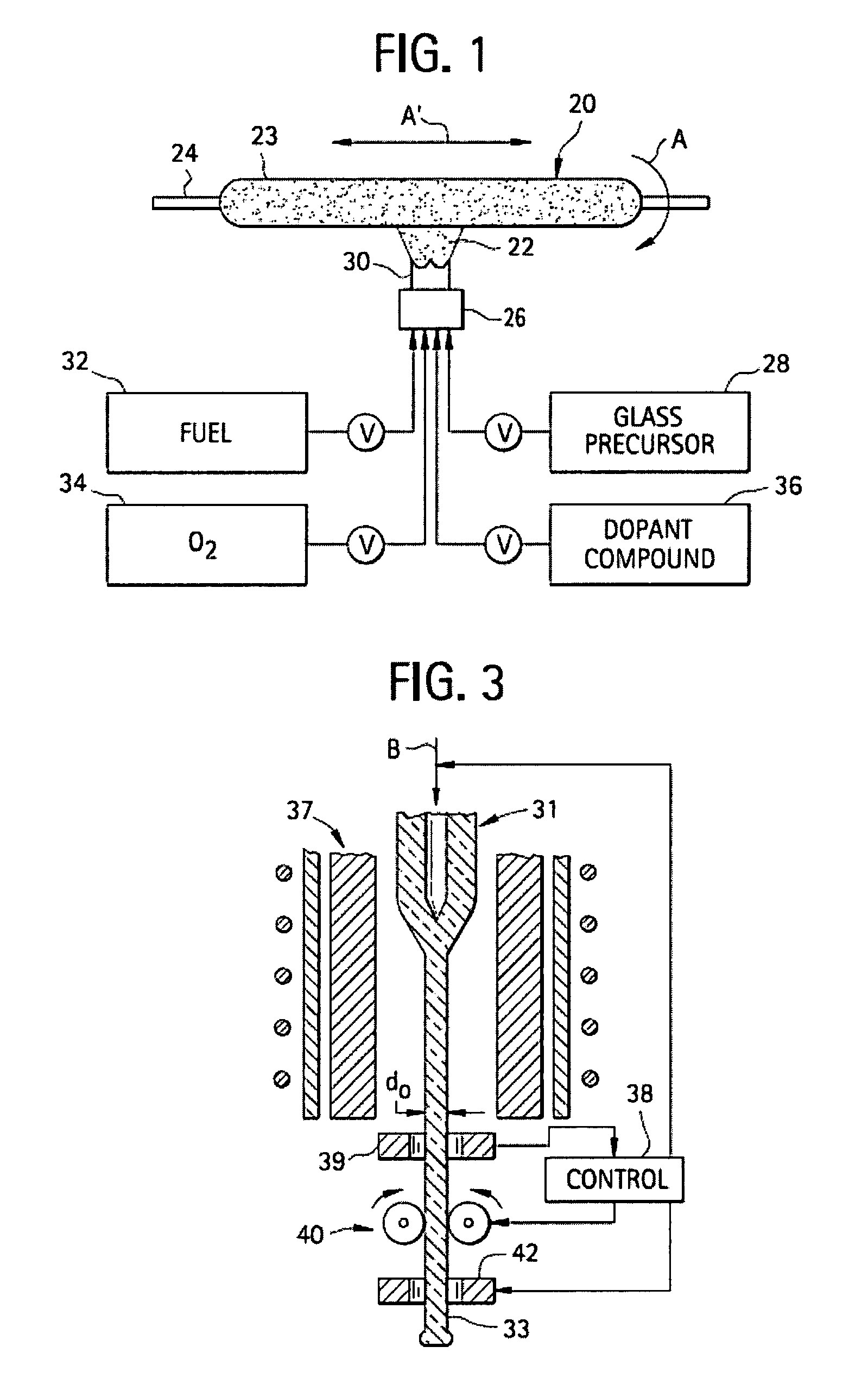
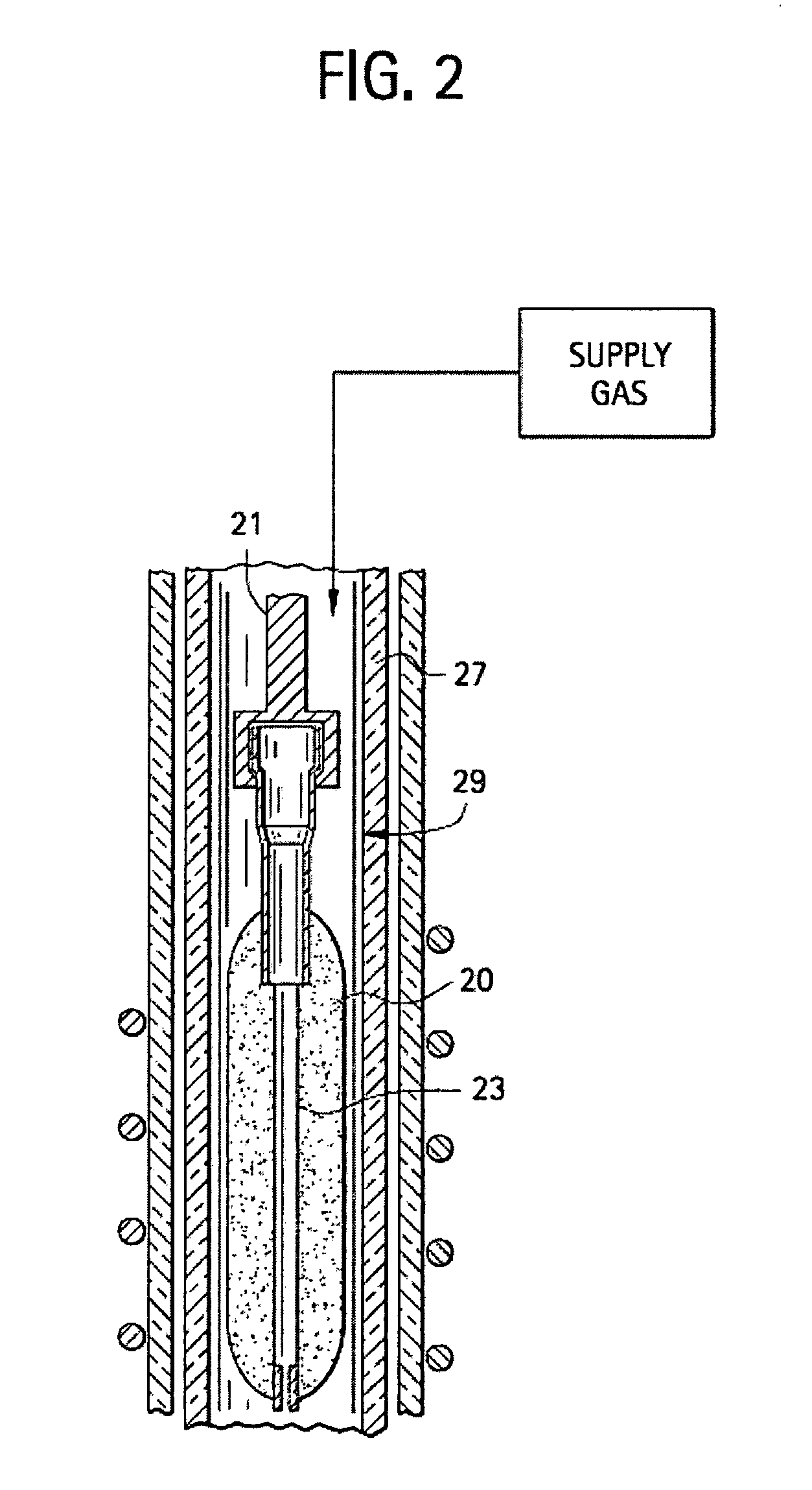
[0067]4600 grams of SiO2 (0.42 g / cc density) soot were deposited via OVD onto a fully consolidated 1 meter long×10 mm diameter step index (0.35 percent delta, 0.33 core / clad diameter ratio) GeO2-SiO2 core-SiO2 clad core cane, thereby resulting in a preform comprising a consolidated core region which was surrounded by a consolidated silica cladding region which in turn was surrounded by a soot silica region. The soot cladding of this assembly was then sintered as follows. The assembly was first dried for 2 hours in an atmosphere consisting of helium and 3 percent chlorine at 1000° C. followed by down driving at 6 mm / min through a hot zone set at 1500° C. (corresponding to a 3° C. / min temperature increase for the outside of the soot preform during the downdrive process) in a 100% oxygen (by volume) atmosphere in order to sinter the soot to an oxygen-seeded overclad blank. The blank was placed for 24 hours in an argon purged holding oven set at 1000° C. to outgas the helium from the bl...

example 2

[0069]200 grams of SiO2 (0.42 g / cc density) soot were deposited via OVD onto a fully consolidated 1 meter long×10.6 mm diameter step index (0.35 percent delta, 0.33 core / clad diameter ratio) GeO2-SiO2 core-SiO2 clad core cane (similar to Example 1), thereby resulting in a preform comprising a consolidated core region which was surrounded by a consolidated silica cladding region which in turn was surrounded by a soot silica region. The soot cladding of this assembly was then sintered as follows. The assembly was first dried for 2 hours in an atmosphere consisting of helium and 3 percent chlorine at 1000° C. followed by down driving at 200 mm / min (corresponding to approximately a 100° C. / min temperature increase for the outside of the soot preform during the downdrive process) through a hot zone set at 1490° C. in a 100 percent oxygen sintering atmosphere. The preform assembly was than re-down driven (i.e., a second time) through the hot zone at 100 mm / min (corresponding to approximat...

example 3

[0070]290 grams of SiO2 (0.47 g / cc density) soot were deposited via OVD onto a fully consolidated 1 meter long ×10.4 mm diameter step index (0.35 percent delta, 0.33 core / clad diameter ratio) GeO2SiO2 core-SiO2 clad core cane (similar to Example 1), thereby resulting in a preform comprising a consolidated core region which was surrounded by a consolidated silica cladding region which in turn was surrounded by a soot silica region. The soot cladding of this assembly was then sintered as follows. The assembly was first dried for 2 hours in an atmosphere consisting of helium and 3 percent chlorine at 1000° C. followed by down driving at 200 mm / min (corresponding to approximately a 100° C. / min temperature increase for the outside of the soot preform during the downdrive process) through a hot zone set at 1490° C. in a 100 percent oxygen sintering atmosphere. The preform assembly was than re-down driven (i.e., a second time) through the hot zone at 100 mm / min (corresponding to approximat...


PUM

PropertyMeasurementUnit
diameteraaaaaaaaaa
mean diameteraaaaaaaaaa
radial widthaaaaaaaaaa

Abstract

Microstructured optical fiber for single-moded transmission of optical signals, the optical fiber including a core region and a cladding region, the cladding region including an annular hole-containing region that contains non-periodically disposed holes. The optical fiber provides single mode transmission and low bend loss.

Description

CROSS-REFERENCE TO RELATED APPLICATIONS[0001]This application claims the benefit of and priority to U.S. Provisional Patent Application No. 60 / 817,721 filed on Jun. 30, 2006, and U.S. Provisional Patent Application No. 60 / 920,425 filed on Mar. 28, 2007, the contents of which are relied upon and incorporated herein by reference in their entirety.BACKGROUND OF THE INVENTION[0002]1. Field of the Invention[0003]The present invention relates generally to optical fibers, and more specifically to microstructured optical fibers.[0004]2. Technical Background[0005]Optical fibers formed of glass materials have been in commercial use for more than two decades. Although such optical fibers have represented a quantum leap forward in the field of telecommunications, work on alternative optical fiber designs continues. One promising type of alternative optical fiber is the microstructured optical fiber, which includes holes or voids running longitudinally along the fiber axis. The holes generally c...

Claims


Application Information

Patent Timeline
Patent Type & Authority Patents(United States)
IPC IPC(8): G02B6/02
CPCC03B37/01446C03B37/01453G02B6/02342G02B6/0365C03B2203/14C03B2203/42G02B6/02333G02B6/02357G02B6/02
Inventor BICKHAM, SCOTT ROBERTSONBOOKBINDER, DANA CRAIGLI, MING-JUNNOLAN, DANIEL ALOYSIUSTANDON, PUSHKAR
Owner CORNING INC
Why Eureka
Try Eureka