
Method for controlling the amount of secondary air

a secondary air and air technology, applied in the direction of electrical control, machines/engines, mechanical equipment, etc., can solve the problems of conversion rate, secondary air is not adaptable to the heating progression of the catalytic converter, afterburning of hot exhaust gas, etc., and achieve the effect of reducing the temperature level of exhaust gas

Inactive Publication Date: 2009-04-21
ROBERT BOSCH GMBH
View PDF23 Cites 0 Cited by
  • Summary
  • Abstract
  • Description
  • Claims
  • Application Information

AI Technical Summary

Benefits of technology

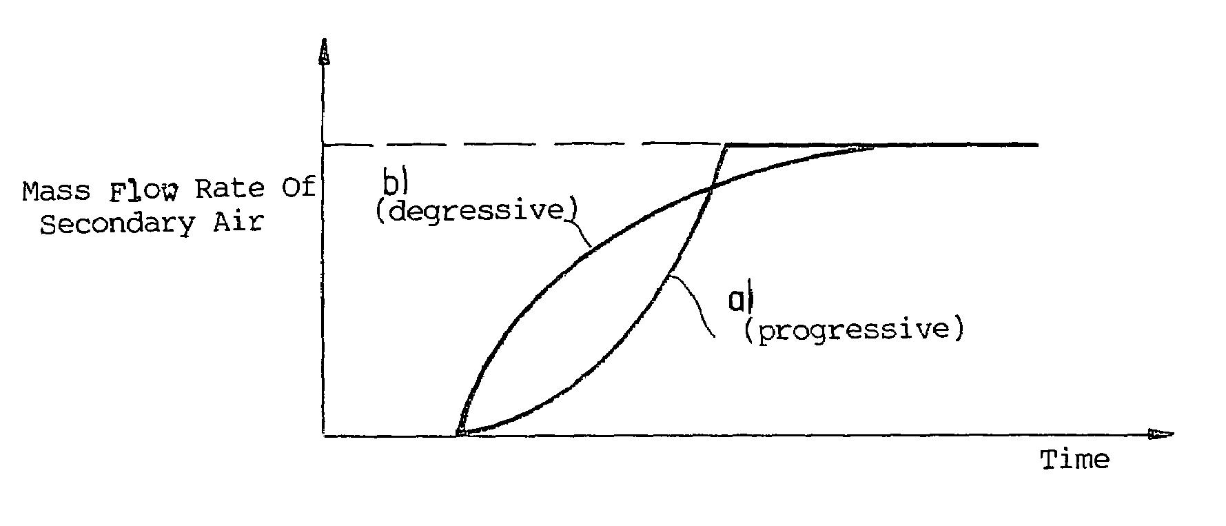
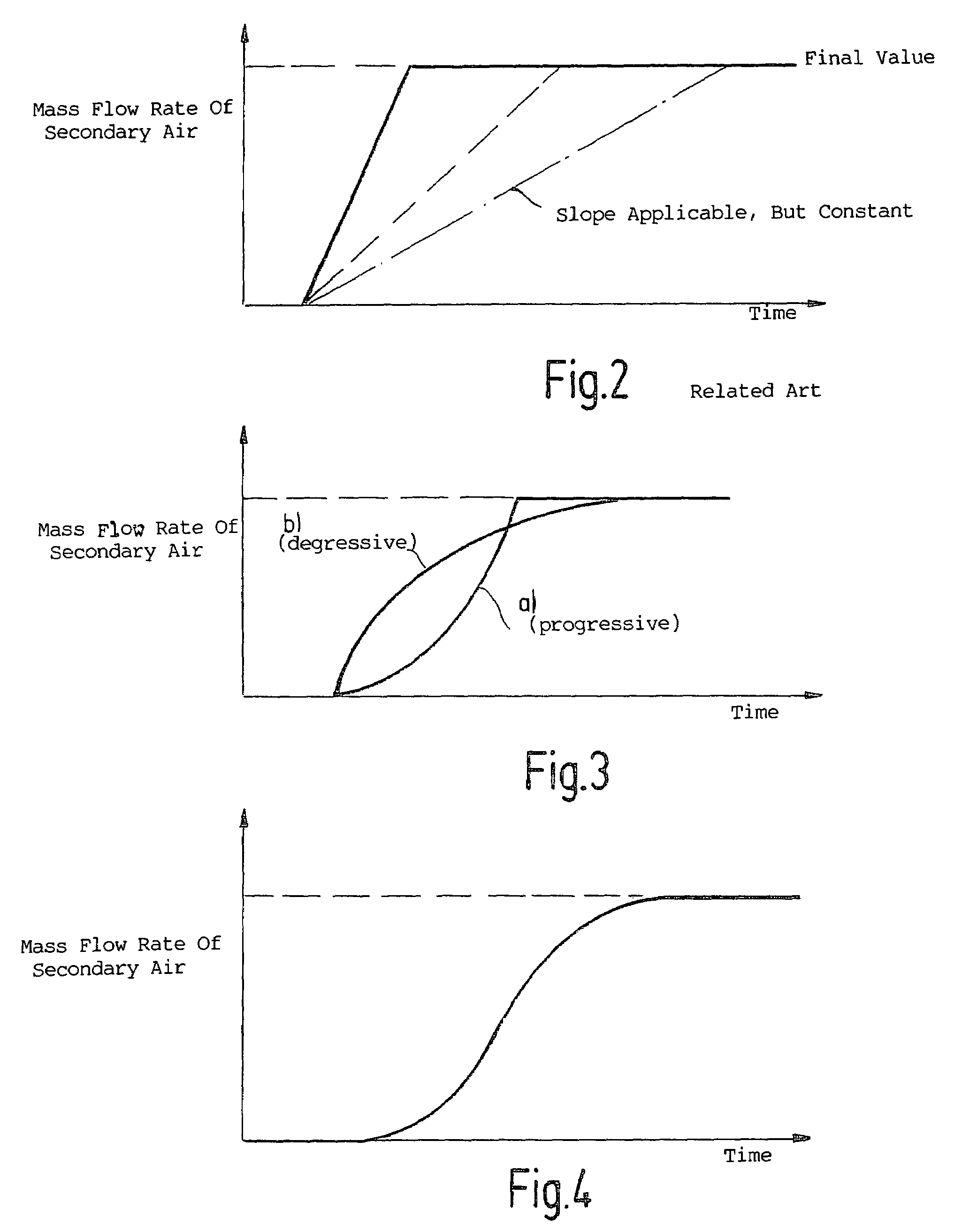
The present invention provides a method for controlling the amount of secondary air in a vehicle to optimize the heating of the catalytic converter and prevent pollutant emissions. The amount of secondary air is increased as a function of the starting conditions and the heating curve of the catalytic converter determined by modeling or measurement. This allows for better conversion rates in the warm-up phase and may dispense with additional heating measures or make them more effective. The start of secondary-air delivery is also selected based on the starting conditions. The change in the amount of secondary air delivered over time is initially progressive and then continuously changes into a degressive curve to ensure optimal air-fuel ratio. This method helps achieve better results in terms of pollutant emissions and temperature levels of the exhaust gas.

Problems solved by technology

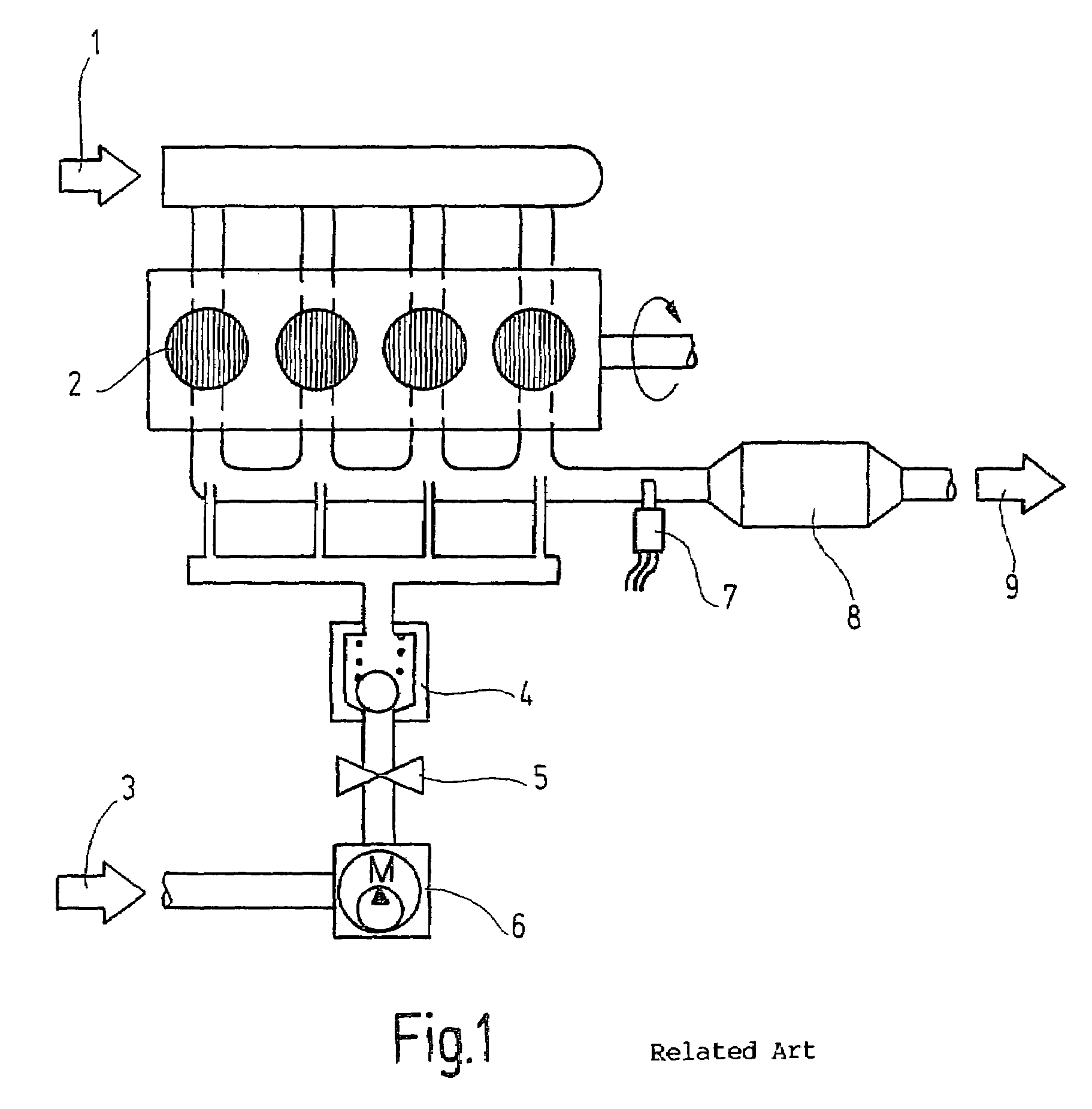
The injection of additional air directly after the combustion chamber results in the afterburning of the hot exhaust gas.
In conventional secondary-air injection systems and methods for controlling the amount of secondary air, it is problematic that the amount of secondary air is not adaptable to the heating progression in the catalytic converter.
This results in a conversion rate, which is not optimal and can lead, in extreme cases, to pollutants such as hydrocarbons (HC) ending up in the exhaust gas (so-called hydrocarbon (HC) breakthroughs).
However, when the heating of the catalytic converter only progresses slowly due to, e.g., unfavorable heat dissipation, the change in the amount of secondary air delivered over time is reduced or, in other words, the progression of the mass flow rate of the secondary air is set to be degressive.
This is slightly greater than λ=1, e.g., λ=1.1, since, because of system tolerances, the air-fuel ratio may also not fall under λ=1 under any circumstances, which results in the formation of a massive amount of hydrocarbons (HC).
On the other hand, too much excess air (λ>>1) reduces the temperature level of the exhaust gas.

Method used


Image

  • Method for controlling the amount of secondary air
  • Method for controlling the amount of secondary air
  • Method for controlling the amount of secondary air

Examples


Embodiment Construction

[0019]An internal combustion engine 2 having a secondary-air injection system is described below in connection with FIG. 1. Internal combustion engine 2, which is supplied intake air 1, has an oxygen sensor 7 situated in the exhaust-gas duct, as well as a catalytic converter 8, which should operate at a conversion rate that is as optimal as possible, in order to prevent harmful exhaust-gas components in exhaust gas 9. Internal combustion engine 2 is supplied secondary air 3 by, e.g., an electric, secondary-air pump 6, which feeds the secondary air through a secondary-air valve 5 and a one-way valve 4, directly after the combustion chamber of internal combustion engine 2. The injection of additional air directly after the combustion chamber results in the afterburning of the hot exhaust gas. The “exothermic reaction” occurring in this context reduces, on one hand, the amount of the exhaust-gas components, hydrocarbons (HC) and carbon monoxide (CO), and heats, on the other hand, the c...


PUM


Abstract

A method for controlling the amount of secondary air of a motor vehicle, which has a device for injecting secondary air. The increase in the injected amount of secondary air is carried out as a function of the starting conditions of the motor vehicle and the heating progression of the catalytic converter determined by modeling and / or measurement, and is variable over time.

Description

FIELD OF THE INVENTION[0001]The present invention relates to method for controlling the amount of secondary air of a motor vehicle that has a device for injecting secondary air.BACKGROUND INFORMATION[0002]The injection of additional air directly after the combustion chamber results in the afterburning of the hot exhaust gas. On one hand, this “exothermic reaction” reduces the amount of the exhaust-gas components, hydrocarbons (HC) and carbon monoxide (CO), and, on the other hand, heats the catalytic converter.[0003]By this means, the conversion rate in the warm-up phase of the catalytic converter is considerably increased, which is particularly necessary for vehicles having very low emissions.[0004]In conventional methods, the secondary air is switched in in an abrupt manner.[0005]In addition, secondary-air injection systems of the applicant are known, in which controllable secondary-air pumps are used whose air mass flow rates are separately measured. The mass of air is then prefer...

Claims


Application Information

Patent Timeline
Patent Type & Authority Patents(United States)
IPC IPC(8): F01N3/00F02D43/00F01N3/20F01N3/22F01N3/24F01N11/00F01P3/20F02D41/04F02D45/00
CPCF01N3/22F01N11/002F01P3/205Y02T10/47Y02T10/40Y02A50/20
Inventor BOERKEL, WOLFGANG
Owner ROBERT BOSCH GMBH
Learn More