Dosimetry using optical emission spectroscopy/residual gas analyzer in conjunction with ion current

a technology of optical emission spectroscopy and residual gas analyzer, which is applied in the direction of material analysis using wave/particle radiation, instruments, vacuum evaporation coating, etc., can solve the problems of difficult to determine the atomic weight of the ions incident on the substrate, the difficulty of determining the boron dose from a measured current, and the difficulty of the plasma immersion ion implantation reactor

Active Publication Date: 2009-05-12
APPLIED MATERIALS INC
View PDF31 Cites 5 Cited by
  • Summary
  • Abstract
  • Description
  • Claims
  • Application Information

AI Technical Summary

Problems solved by technology

In contrast, plasma immersion ion implantation reactors present a difficult problem in dosimetry.
Typically, the atomic weight of the ions incident on the substrate cannot be precisely determined because such a reactor employs a precursor gas containing the desired ion implantation species as well as other species.
As a result, determining the boron dose from a measured current is difficult.
Another difficulty in implementing dosimetry in a plasma immersion ion implantation reactor is that the plasma ions impact the entire substrate continuously, so that it is difficult to effect a direct measurement above the substrate of the total ion current to the substrate.
Plasma immersion ion implantation reactors employing D.C. (or pulsed D.C.) plasma source power are susceptible to drift in the plasma ion current due to deposition of material on internal reactor components from the plasma.
One problem with such an arrangement is that the current measurement cannot distinguish between different atomic species, and therefore cannot provide an accurate measurement of the species of interest (e.g., boron).
Another problem is that the transmission of the measured current from the current sensor inside the cathode interior to an external controller or processor can be distorted by the noisy electromagnetic environment of the plasma reactor.
Another problem is that the orifice in the cathode constitutes an intrusion upon the ideal plasma environment, because the orifice can distort the electric field in the vicinity of the substrate periphery.
Furthermore, plasma passing through the orifice can cause problems by either sputtering the orifice surfaces or by depositing on the orifice interior surfaces, requiring the periodic cleaning of the orifice interior.
Moreover, real-time dose measurement in such a reactor is difficult.
However, a real-time does control is more and more in need as the feature size becomes smaller and smaller in the semiconductor devices.

Method used


Image

  • Dosimetry using optical emission spectroscopy/residual gas analyzer in conjunction with ion current
  • Dosimetry using optical emission spectroscopy/residual gas analyzer in conjunction with ion current
  • Dosimetry using optical emission spectroscopy/residual gas analyzer in conjunction with ion current

Examples


Embodiment Construction

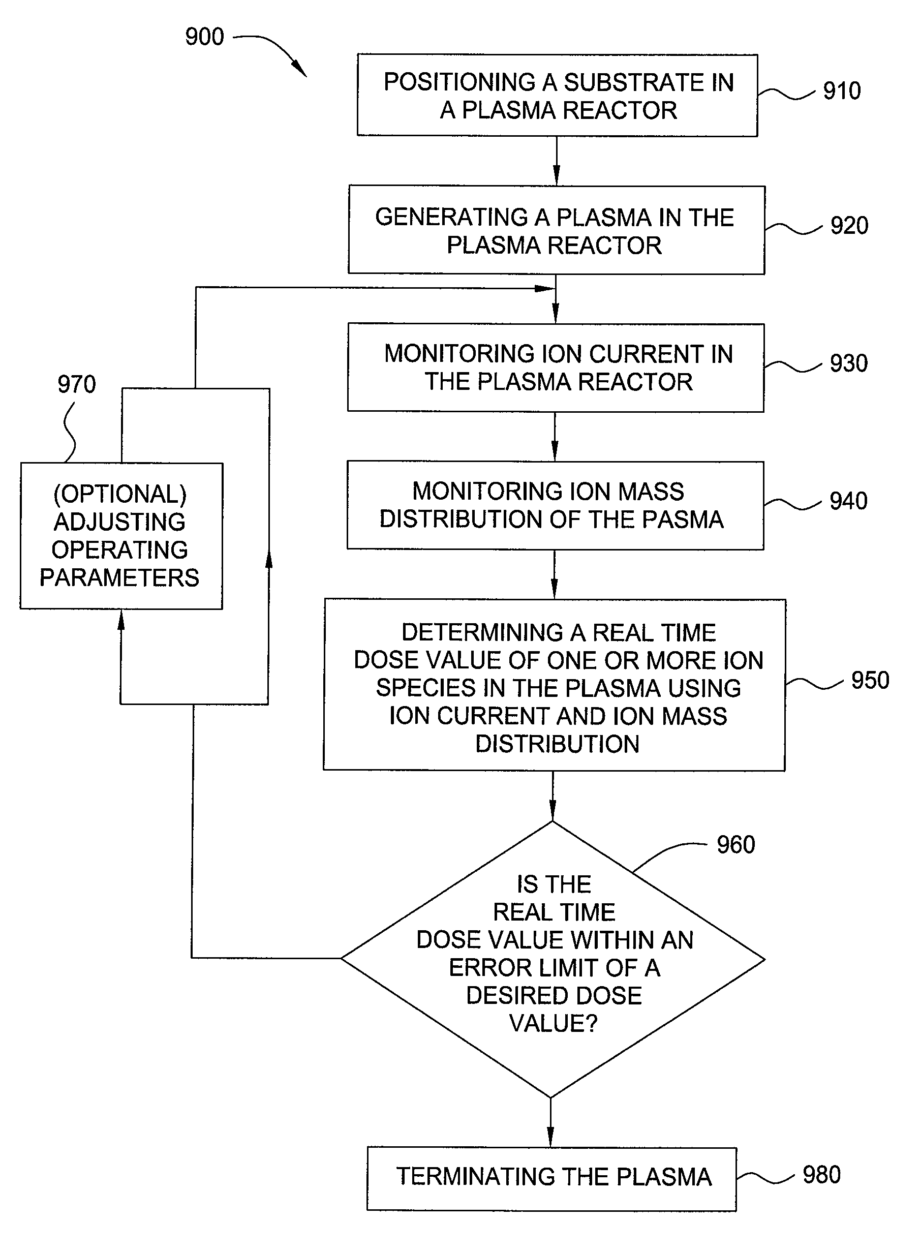
[0023]Embodiments of the present invention provide methods for controlling ion dosages in real time during plasma processes and apparatus for performing the methods.

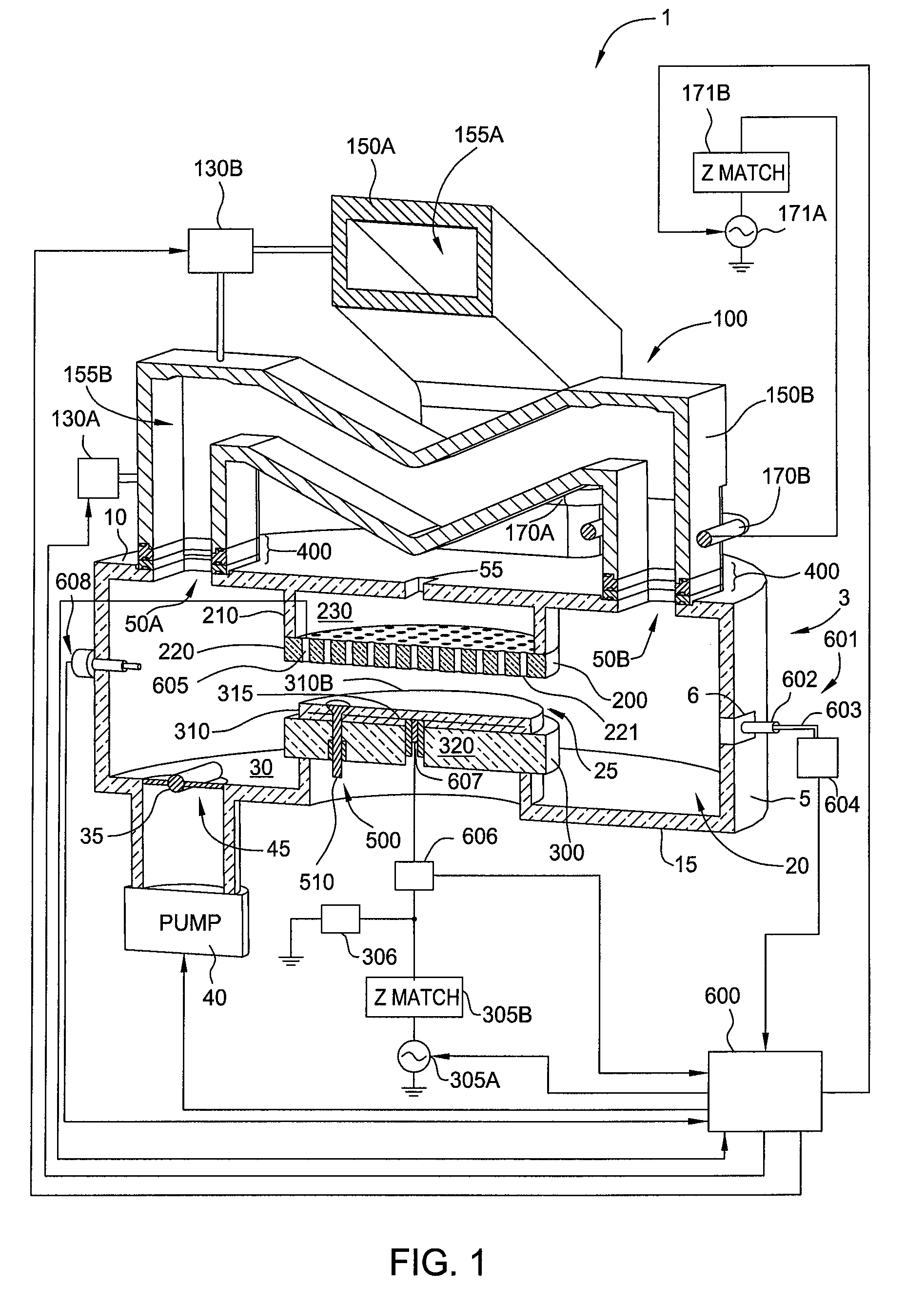
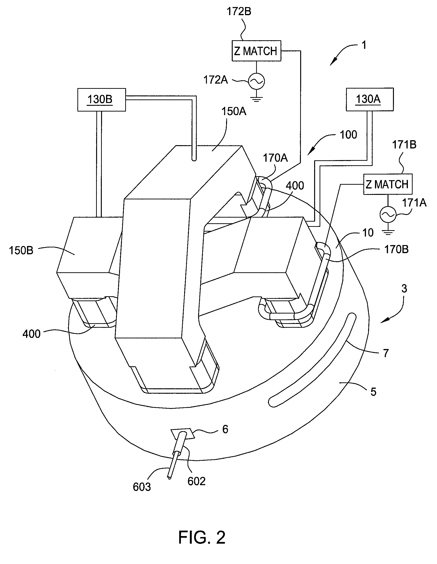
[0024]FIG. 1 schematically illustrates an isometric cross-sectional view of a plasma chamber 1 in accordance with one embodiment of the present invention. The plasma chamber 1 may be configured for a plasma enhanced chemical vapor deposition (PECVD) process, a high density plasma chemical vapor deposition (HDPCVD) process, an ion implantation process, an etch process, and other plasma processes.

[0025]The plasma chamber 1 comprises a toroidal plasma source 100 coupled to a body 3 of the plasma chamber 1. The body 3 comprises sidewalls 5 coupled to a lid 10 and a bottom 15, which bounds an interior volume 20. Other examples of the plasma chamber 1 may be found in U.S. Pat. No. 6,939,434, filed Jun. 5, 2002 and issued on Sep. 6, 2005 and U.S. Pat. No. 6,893,907, filed Feb. 24, 2004 and issued May 17, 2005, both of which are...


PUM

PropertyMeasurementUnit
wavelengthsaaaaaaaaaa
total ion currentaaaaaaaaaa
optical emissionaaaaaaaaaa

Abstract

The present invention generally provides methods and apparatus for controlling ion dosage in real time during plasma processes. In one embodiment, ion dosages may be controlled using in-situ measurement of the plasma from a mass distribution sensor combined with in-situ measurement from an RF probe.

Description

CROSS-REFERENCE TO RELATED APPLICATIONS[0001]This application is a continuation-in-part of co-pending U.S. patent application Ser. No. 10 / 971,772, filed Oct. 23, 2004, which is herein incorporated by reference.BACKGROUND OF THE INVENTION[0002]1. Field of the Invention[0003]Embodiments of the present invention generally relate to method and apparatus for processing a substrate. Particularly, embodiments of the present invention relate to methods and apparatus for monitoring dosages of one or more species during plasma processing of semiconductor substrates.[0004]2. Description of the Related Art[0005]It is important to control ion dosage during plasma processes, such as plasma enhanced chemical vapor deposition (PECVD) process, high density plasma chemical vapor deposition (HDPCVD) process, plasma immersion ion implantation process (P3I), and plasma etch process. Ion implantation processes in integrated circuit fabrication particularly require instrumentation and control to achieve a...

Claims


Application Information

Patent Timeline
Patent Type & Authority Patents(United States)
IPC IPC(8): H01L21/00
CPCC23C14/48C23C14/54H01J37/321H01J37/32412H01J37/32935G01N21/00G01N23/00
Inventor RAMASWAMY, KARTIKCHO, SEON-MEETANAKA, TSUTOMUFOAD, MAJEED A.
Owner APPLIED MATERIALS INC
Why Eureka
Try Eureka