
DC-DC converter

a converter and dc technology, applied in the direction of dynamo-electric converter control, process and machine control, instruments, etc., can solve the problems of low power conversion efficiency, unfavorable increase of manufacturing costs, and malfunction of devices connected to switching power sources, so as to reduce the power consumption of the oscillator, improve the switching efficiency, and reduce the loss of switching.

Active Publication Date: 2009-06-02
SANKEN ELECTRIC CO LTD
View PDF3 Cites 30 Cited by
  • Summary
  • Abstract
  • Description
  • Claims
  • Application Information

AI Technical Summary

Benefits of technology

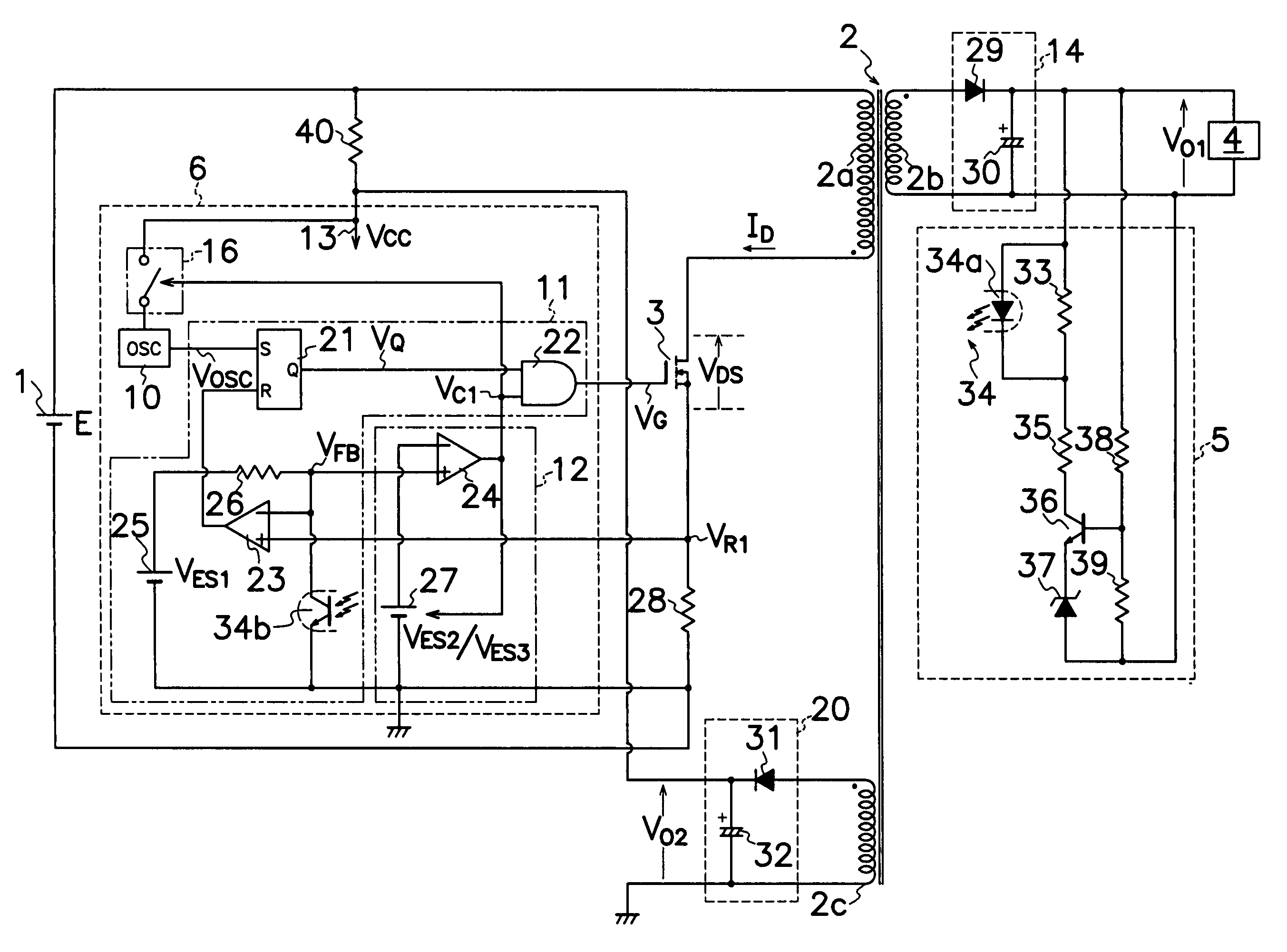
The present invention is a DC-DC converter that includes a transformer and a switching element connected to a DC power source. The converter has an output voltage detector, a control circuit, and a power control circuit. The control circuit produces on-off signals to the switching element to regulate the output voltage. The power control circuit inhibits production of pulse signals during the intermittent operation of the switching element to reduce switching loss and improve switching efficiency. The power control circuit also stops power supply to the oscillator during the output cessation period to decrease power consumption. The control circuit has quick response times and can produce a stable DC output without large output ripple.

Problems solved by technology

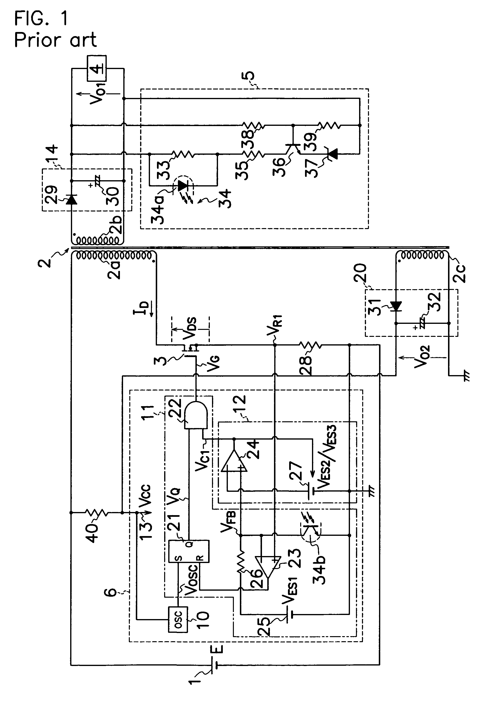
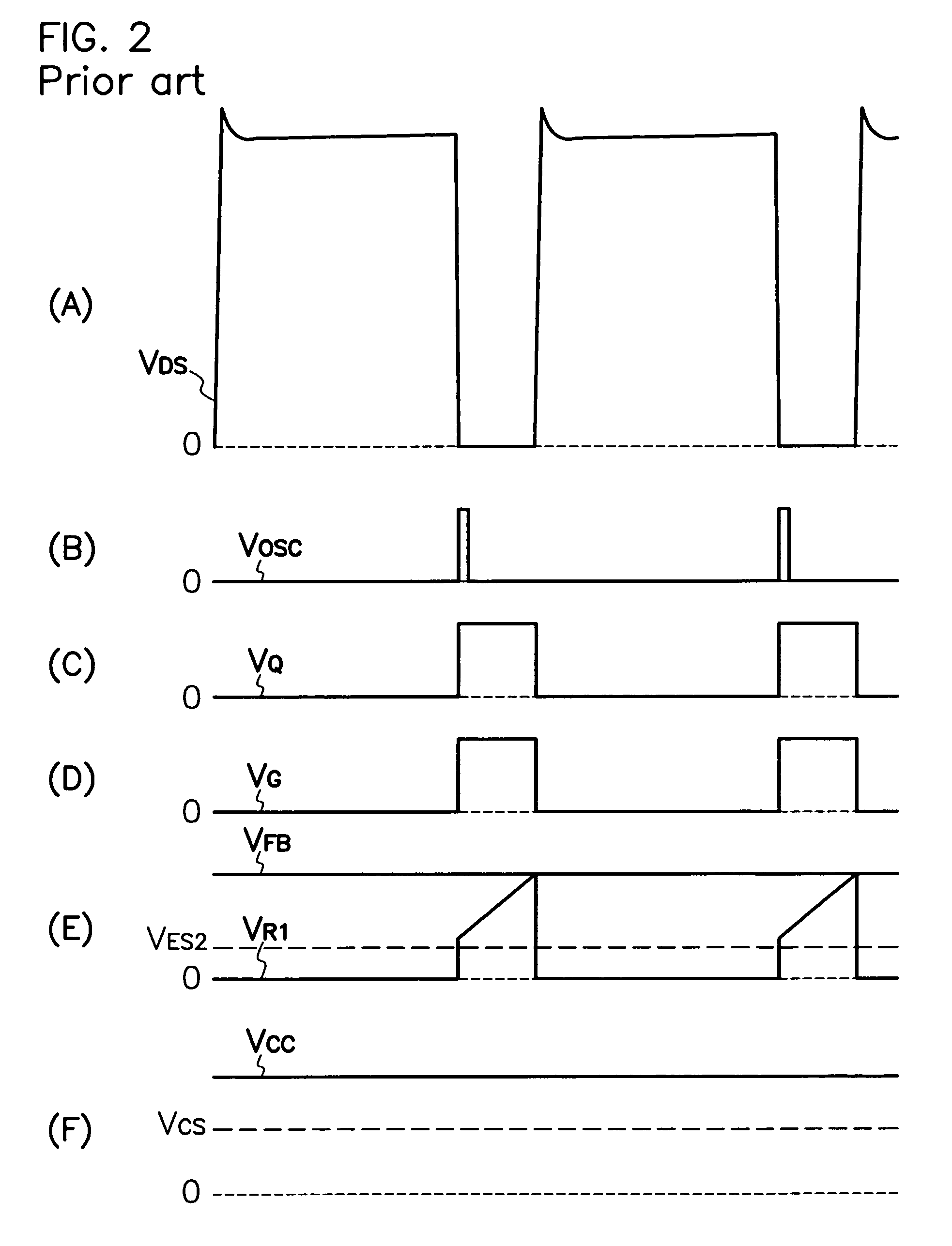
DC-DC converter shown in FIG. 1, however, has a drawback of low efficiency in power conversion during the light load period because oscillator 10 continues to produce pulse signals VOSC during the intermittent operation of MOS-FET 3 as undesirably the converter represents power consumption of very unchanged level between the light and non-light load periods.
However, the DC-DC converter shown in the foregoing reference interrupts whole drive power to control circuit, and therefore, suspends power supply to power supplies for producing reference voltages, comparators, amplifiers or the like other than oscillator each time switching element comes to the intermittent operation.
Also, as it takes a necessary time until reference voltages inside of control circuit reach a steady level from no-power supplied condition, similarly to upon power-on, large output ripples may appear in DC output due to the delayed response when switching element is converted from the intermittent operation to the ordinary operation so that output ripples may disadvantageously cause malfunction in devices connected to the switching power source.
To suppress output ripples, rectifying smoother needs a capacitor of large capacitance, or electric current to load has to be reduced to a small amount, however, these measures may unfavorably increase costs in manufacture due to employment of large capacitance capacitor, expanded size of the converter and shortage of supplied power by reduction in electric current to load.

Method used


Image

  • DC-DC converter
  • DC-DC converter
  • DC-DC converter

Examples


first embodiment

[0032]FIG. 7 shows power control circuit 16 which comprises a P-channel MOS-FET 17 as a switch element connected between a drive power source 13 and oscillator 10 to receive drive power VCC from drive power source 13. MOS-FET 17 is turned off when second comparator 24 of intermittent controller 12 produces the output of low voltage level VC1 to AND gate 22 of signal output circuit 11. Power control circuit 16 comprises a series circuit of resistors 45 and 46 and N-channel MOS-FET 47 connected in series between a junction of drive power source 13 and P-channel MOS-FET 17 and ground; a gate terminal of P-channel MOS-FET 17 is connected to a junction of resistors 45 and 46; and a gate terminal of N-channel MOS-FET 47 is connected to output terminal of second comparator 24 through a resistor 48.

[0033]FIG. 8 shows voltage waveforms in selected location of the circuit when MOS-FET 3 is converted to the intermittent operation during the light load period. When second comparator 24 produces...

second embodiment

[0034]FIG. 9 illustrates power control circuit 16, but otherwise, oscillator 10 comprises a signal generator 7 for producing pulse signals VOSC, and a power supplying circuit 8 for feeding drive power VCC to signal generator 7 of oscillator 10. Power supplying circuit 8 comprises a feed PNP transistors 9a to 9c as switches connected between drive power source 13 and signal generator 7 to receive drive power VCC from drive power source 13. Power control circuit 16 turns feed PNP transistors 9a to 9c off when second comparator 24 produces control signal VC1 of low voltage level to AND gate 22 of signal output circuit 11. Drive power VCC is modulated to a constant voltage through a voltage regulator 49 on which drive power VCC is applied, and supplied to oscillator 10. Power control circuit 16 comprises a series circuit of a first control PNP transistor 19, a resistor 50 and a second control NPN transistor 59 connected between voltage regulator 49 and ground, and a base terminal of sec...


PUM


Abstract

A DC-DC converter is provided with a control circuit 6 which comprises a drive signal generator 11 for producing on-off signals to a control terminal of a MOS-FET 3 in synchronization with pulse signals VOSC from an oscillator 10; an intermittent controller 12 for producing a control signal VC1 to drive signal generator 11 in response to the level of detection signal from an output voltage detector 5 to convert MOS-FET 3 to the intermittent operation during the light load period; and a power control circuit 16 for ceasing power supply VCC to oscillator 10 in response to control signal VC1 from intermittent controller 12 to stop production of pulse signal VOSC from oscillator 10 for the cessation term of MOS-FET 3 during the intermittent operation.

Description

TECHNICAL FIELD[0001]This invention relates to a DC-DC converter, in particular, of the type capable of reducing power consumption by stopping oscillation of an oscillator when a switching element is shifted to an intermittent operation during the light load period.BACKGROUND OF THE INVENTION[0002]A known DC-DC converter comprises a switching element which is turned on and off to intermittently convert DC voltage from a DC power source into an electric power of high frequency, and a transformer for converting the electric power into a stabilized DC power then supplied to an electric load through a rectifying smoother. For example, a prior art DC-DC converter shown in FIG. 1 comprises a primary winding 2a of a transformer 2 and an N-channel MOS-FET 3 as a switching element connected in series to a DC power source 1; secondary and auxiliary windings 2b and 2c of transformer 2 electro-magnetically coupled to primary winding 2a and each other; a main rectifying smoother 14 which has a m...

Claims


Application Information

Patent Timeline
Patent Type & Authority Patents(United States)
IPC IPC(8): H02M3/335G05F5/00H02M5/257H02M5/42H02M7/537
CPCH02M1/36H02M3/33507H02M3/33523H02M3/28
Inventor YAMADA, TOMOYASU
Owner SANKEN ELECTRIC CO LTD
Learn More