Non-linear wavefront coding systems and methods

a coding system and wavefront technology, applied in the field of non-linear wavefront coding systems and methods, can solve the problems of difficult to accurately and fully image real objects, image will be out of focus, and traditional imaging systems suffer from a number of setbacks, so as to reduce aberrations

Active Publication Date: 2009-06-23
CDM OPTICS
View PDF33 Cites 19 Cited by
  • Summary
  • Abstract
  • Description
  • Claims
  • Application Information

AI Technical Summary

Benefits of technology

[0009]In another embodiment, a method reduces aberrations in a wavefront imaged by an optical system having a non-linear detector. A wavefront of electromagnetic radiation from an object imaged to the non-linear detector is encoded. Data from the non-linear detector is digitally converted to form a digital representation of the image captured by the non-linear detector. The detected image is linearized to form a linearized image. The linearized image is filtered to reverse effects of wavefront coding to form a final image.

Problems solved by technology

Traditional imaging systems, however, suffer from a number of setbacks.
First, such systems typically have a relatively low depth of field, making it difficult to accurately and fully image real objects.
Since the range of the depth of field is inherently limited, there are problems associated with imaging an object wherein its dimensions exceed the depth of field, as some portion of the image will be out of focus and blurry.
However, overcoming low depth of field in these ways significantly reduces the optical energy at the image plane and decreases image resolution.
The decrease of optical energy and increase in image noise may be at least partially remedied by adding significant illumination to the traditional imaging system; but this adds weight, complexity and expense to the design.
Misfocus-related aberrations, and control of such, present other problems in traditional imaging systems.
Misfocus-related aberrations include, for example, chromatic aberration, curvature of field, spherical aberration, astigmatism, and temperature or pressure related misfocus; such aberrations cause image blurring and loss of resolution, and can make image colors appear shifted or otherwise incorrect.
Traditional imaging systems remedy such aberrations by adding lens elements that increase cost, weight and overall lens complexity.
Consequently, traditional imaging systems must make a trade-off between (a) good images that generally require complex optical designs and (b) lower quality images that reduce size, weight, and / or the number of optical elements in the optical design.
Photographic film and many other detectors do not, however, demonstrate such a linear response.

Method used


Image

  • Non-linear wavefront coding systems and methods
  • Non-linear wavefront coding systems and methods
  • Non-linear wavefront coding systems and methods

Examples


Embodiment Construction

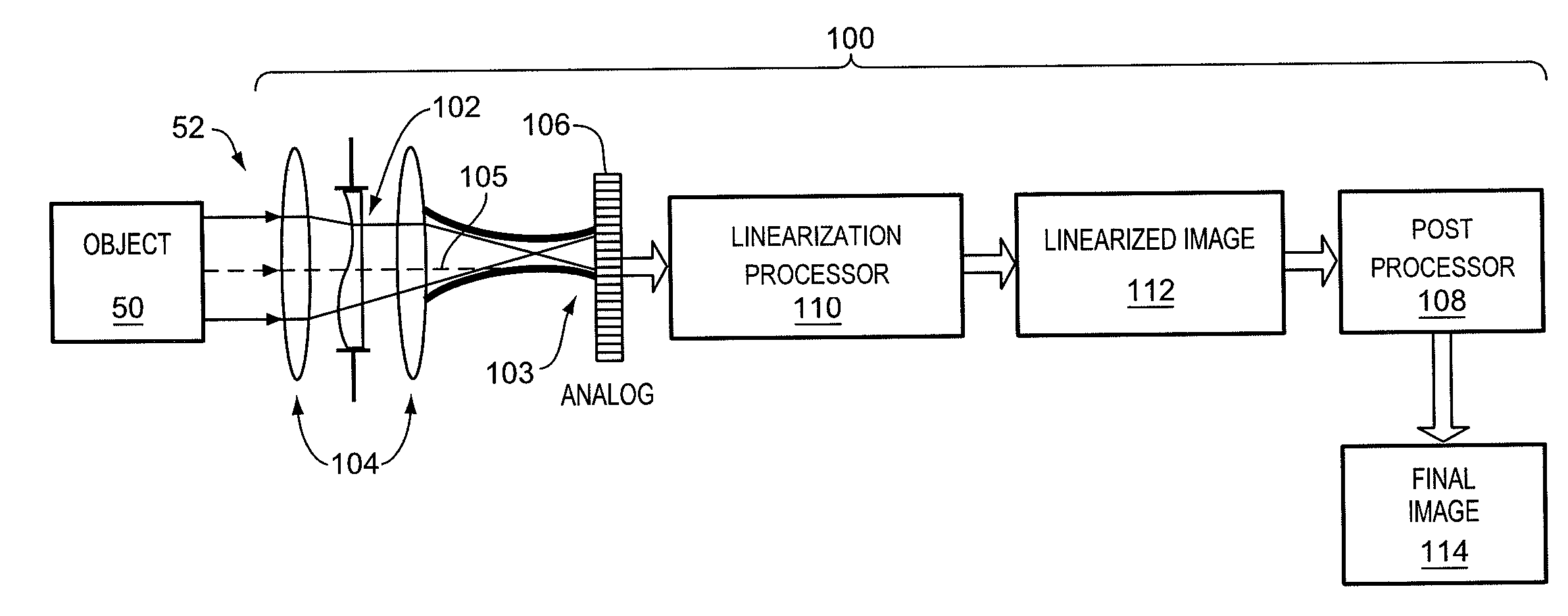
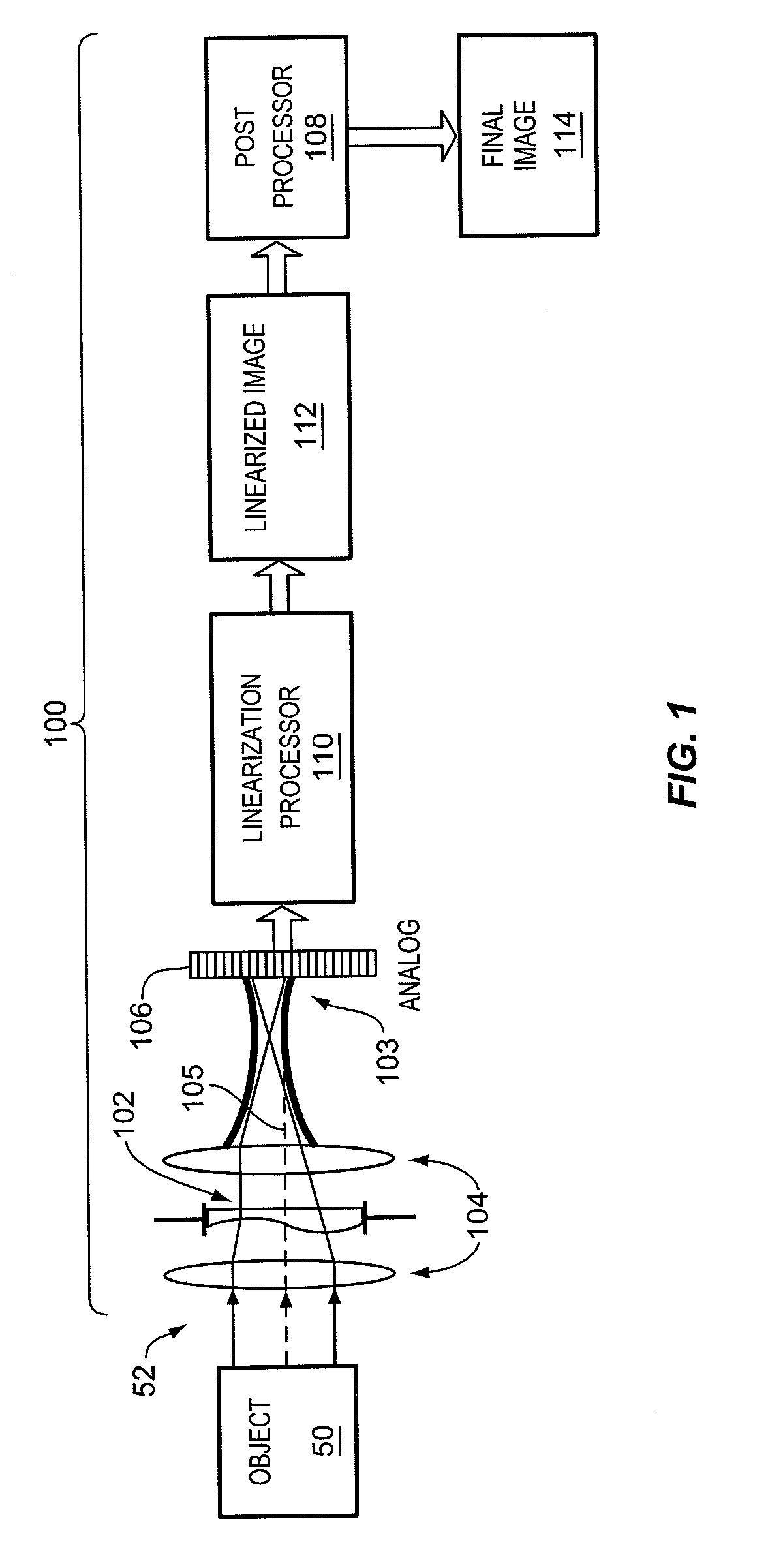
[0018]A non-linear imaging system 100 that extends depth of field is shown generally in FIG. 1. System 100 includes (a) optics 102 that may, for example, take the form of an optical phase mask, (b) optical elements (e.g., lenses and / or mirrors) 104, (c) a non-linear detector 106, and (d) a post processor 108. Optics 102 and elements 104 cooperate to image electromagnetic radiation 52 from object 50 to an intermediate image 103, which is then captured by non-linear detector 106. Electromagnetic radiation 52 may be in one or more of the visible spectrum, infrared spectrum, ultraviolet spectrum, radio wave spectrum, or another part of the electromagnetic spectrum. Optics 102“encode” the optical wavefront within system 100, as described below, to spatially blur points of imaged object 50 about intermediate image 103 (e.g., along optical axis 105).

[0019]Intermediate image 103 does not, therefore, occupy a single focal point as in traditional imaging systems. An exemplary ray path-based e...


PUM


Abstract

Systems and methods reduce aberrations in a wavefront imaged by an optical system having a non-linear detector. A wavefront of electromagnetic radiation from an object imaged to the non-linear detector is encoded. Data from the non-linear detector is digitally converted to form a digital representation of the image captured by the non-linear detector. The detected image is linearized to form a linearized image. The linearized image is filtered to reverse effects of wavefront coding to form a final image.

Description

RELATED APPLICATIONS[0001]This application claims priority to U.S. provisional application Ser. No. 60 / 449,944, filed 25 Feb. 2003 and hereby incorporated by reference.BACKGROUND[0002]Traditional optical imaging system design has focused on the combination of certain optics with an image detector. The optics may include, for example, lenses that focus and magnify images. The image detector may be a non-linear detector (e.g. film) or a linear detector (e.g., CCD array) that detects the optical radiation to form an image. The detected image may then undergo traditional image processing techniques—such as edge sharpening and color filter array (CFA) color interpolation—to improve certain aspects of the image. Thus, traditional optics in imaging systems are designed to form images at the detector that are sharp and clear over a range of field angles, illumination wavelengths, temperatures, and focus positions.[0003]Traditional imaging systems, however, suffer from a number of setbacks. ...

Claims


Application Information

Patent Timeline
Patent Type & Authority Patents(United States)
IPC IPC(8): G01J1/20G02B27/00G06T5/00
CPCG02B27/0025G06T5/00
Inventor CATHEY, JR., W. THOMASGREENGARD, ADAM DOUGLAS
Owner CDM OPTICS
Why Eureka
Try Eureka