System and method for providing a clock and data recovery circuit with a self test capability

a clock and data recovery circuit technology, applied in the field of clock and data recovery circuit manufacturing, can solve the problems of increasing the complexity of implementation, high cost of testing equipment, so as to reduce the amount of time, cost and test equipment, and increase the manufacturing profit margin

a clock and data recovery circuit technology, applied in the field of clock and data recovery circuit manufacturing, can solve the problems of increasing the complexity of implementation, high cost of testing equipment, so as to reduce the amount of time, cost and test equipment, and increase the manufacturing profit margin

US7555091B1Active Publication Date: 2009-06-30NAT SEMICON CORP

Image

  • System and method for providing a clock and data recovery circuit with a self test capability
  • System and method for providing a clock and data recovery circuit with a self test capability
  • System and method for providing a clock and data recovery circuit with a self test capability

Examples


Embodiment Construction

[0041]FIGS. 1 and 10 and the various embodiments used to describe the principles of the present invention in this patent document are by way of illustration only and should not be construed in any way to limit the scope of the invention. Those skilled in the art will understand that the principles of the present invention may be implemented in any type of suitably arranged clock and data recovery system.

[0042]To simplify the drawings the reference numerals from previous drawings will sometimes not be repeated for structures that have already been identified.

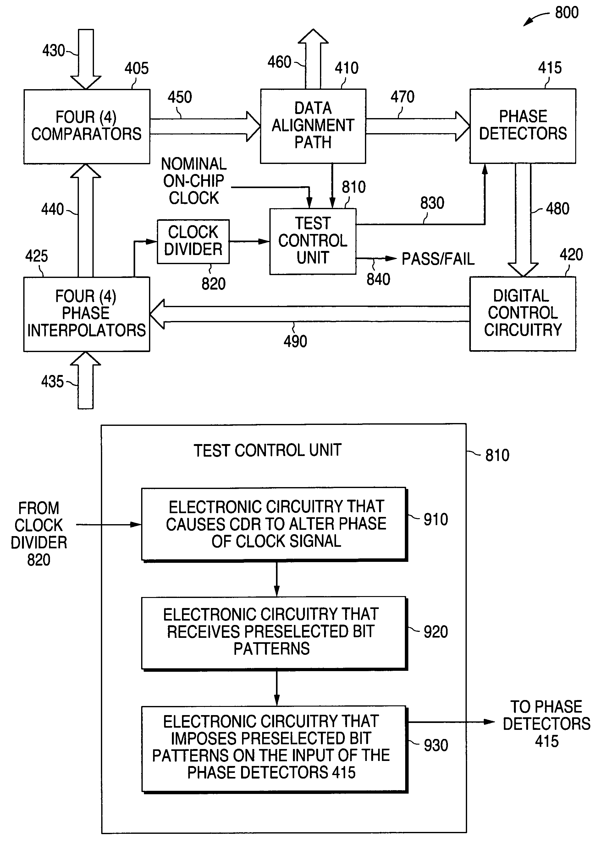
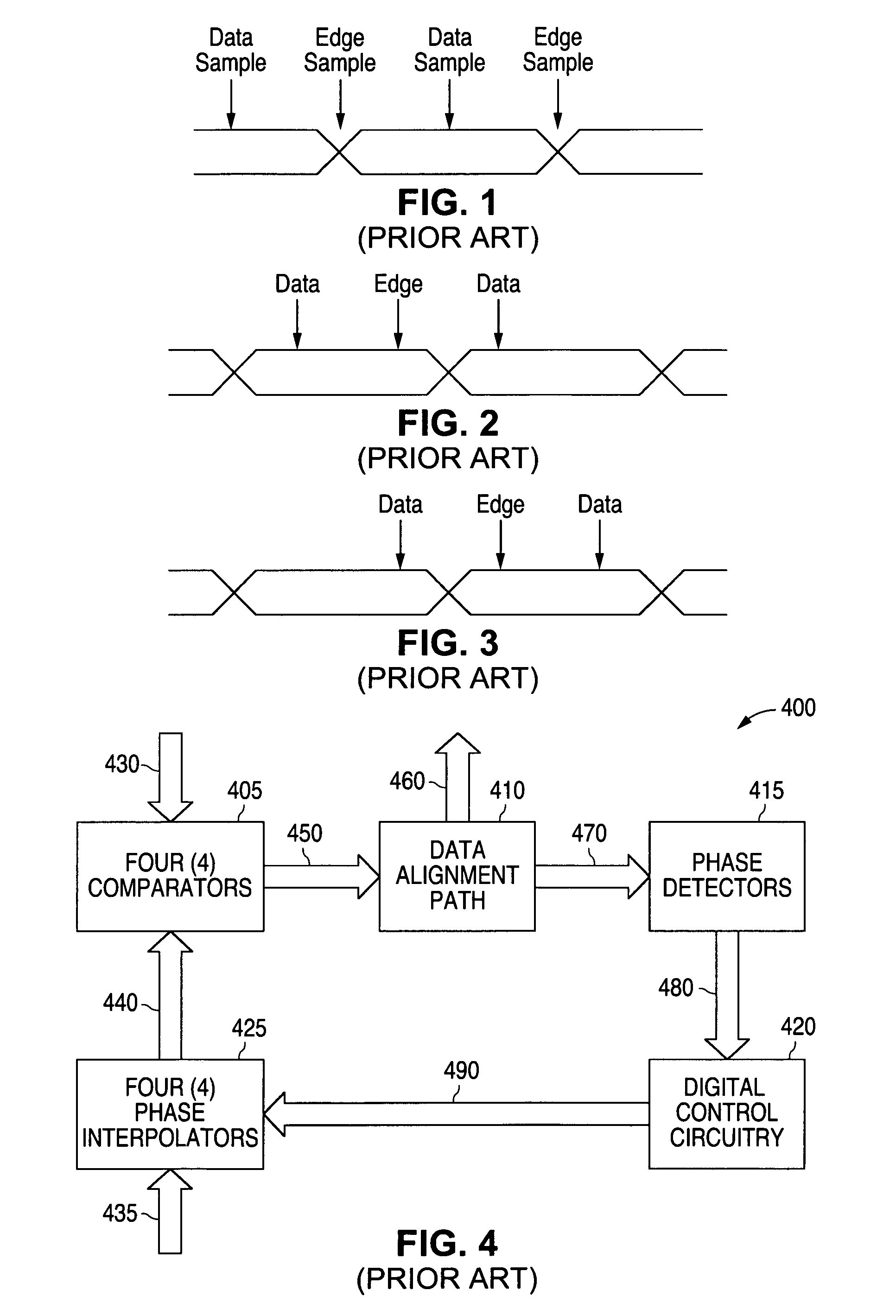
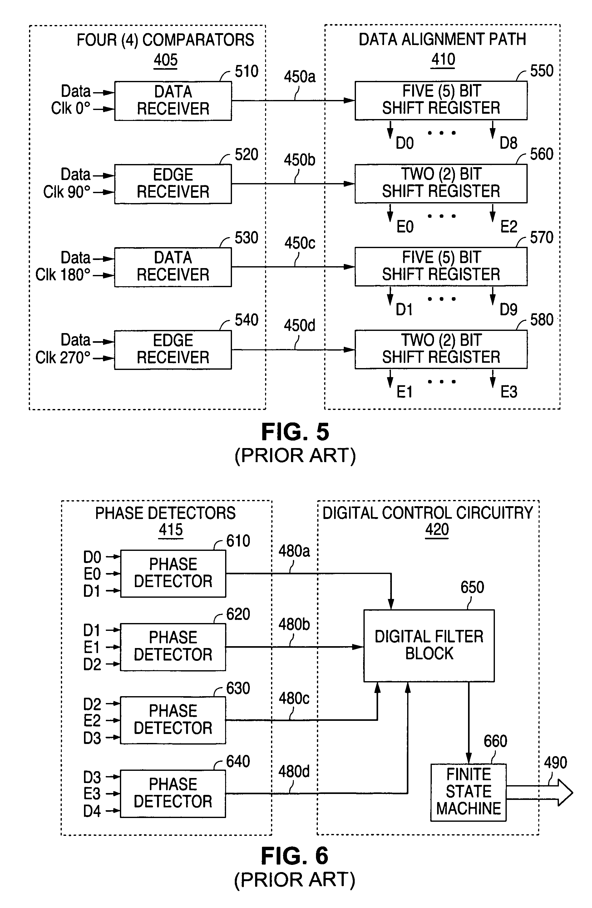
[0043]In order to better understand the principles of the present invention a description of a prior art clock and data recovery system will first be given. FIG. 4 illustrates a schematic diagram of a prior art clock and data recovery circuit 400 that employs phase interpolator architecture. The clock and data recovery circuit 400 requires four (4) clock phases that are generated by a phase locked loop (PLL) (not shown in FIG. 4)...


PUM


Abstract

A system and method is disclosed for providing a clock and data recovery circuit with a self test capability. A test control unit is provided that causes the clock and data recovery circuit to continuously alter a phase of an interpolated clock signal. A user selects a preselected bit pattern that causes the digital control circuitry of the clock and data recovery circuit to advance or retard the phase of the interpolated clock signal. The test control unit compares the advanced or retarded phase of the interpolated clock signal with a reference clock signal to determine a frequency difference between the two clock signals. The test control unit uses the frequency difference to determine the test status of the clock and data recovery circuit.

Description

TECHNICAL FIELD OF THE INVENTION[0001]The present invention is generally directed to the manufacture of clock and data recovery circuits for semiconductor devices and, in particular, to a system and method for providing a clock and data recovery circuit having a self test capability.BACKGROUND OF THE INVENTION[0002]A clock and data recovery (CDR) circuit is an integral part of a modern data communication system. A CDR circuit is connected to and interfaces with a data signal line that carries incoming data. The CDR circuit performs the function of extracting the incoming data and clock information from the incoming data stream. This function is typically performed with an electronic control loop that detects the incoming data. Based on the data edge locations in time, the electronic control loop makes a determination of the instantaneous phase of the data.[0003]The electronic control loop subsequently aligns the electronic control loop's own internal clock with the phase of the inco...

Claims


Application Information

Patent Timeline
30 Jun 2009
Publication
US7555091B1
IPC
H03D3/24
CPC
G01R31/31715; H03L7/0814; H03L7/087; H03L7/091; H04L1/24; H04L7/0079; G01R31/31726; H04L7/0025
Inventors
LEWICKI, LAURENCE D.; OBEIDAT, AMJAD T.