Method for adjusting an output parameter of a circuit

a technology of applied in the direction of positive temperature coefficient thermistors, resistive material coatings, instruments, etc., can solve the problems of unavoidable statistical spread of device parameters, output voltage and temperature coefficient, and the dependence of output parameters on resistors, etc., to improve the trimming performance of analog electric circuits

Inactive Publication Date: 2009-07-07
SENSORTECHNICS
View PDF9 Cites 9 Cited by
  • Summary
  • Abstract
  • Description
  • Claims
  • Application Information

AI Technical Summary

Benefits of technology

[0016]The present invention improves trimming performance of analog electric circuits, such as voltage references, potentially trimmable by the manufacturer and also potentially trimmable by the user in some cases. Electro-thermal trimming of thermally-trimmable resistors is used to trim one or more of the plurality of resistors in or associated with an analog electric circuit. The TCR of each of a subset of a plurality of electro-thermally-trimmable resistors can be trimmed independently from the resistance in order to adjust the output parameter of an analog electric circuit without changing other parameters that would be affected by a change in resistance.
[0018]A pair of electro-thermally-trimmable resistors, external to a voltage reference integrated circuit, such as R5 and R6 in FIG. 20, where the resistance values and RTCR are both trimmable, can be used as a voltage divider to trim both the output voltage and temperature coefficient of the output voltage of a voltage reference. If the output voltage without R5 and R6 has a substantial linear component of temperature variation, then trimming of RTCR of R5 and R6 can significantly reduce or eliminate such linear component of temperature variation.
[0020]Considering R1 and R2 in FIG. 20, in certain typical embodiments of voltage reference circuits, these two resistors are preferably trimmed to a predetermined resistance value. Additionally, they should preferably have the same TCR. A pair of electro-thermally-trimmable resistors as R1 and R2, where the resistance values and RTCR are both trimmable, can be used to change or improve the temperature behavior of the output voltage.
[0021]Considering R3 and R4 in FIG. 20, In certain typical embodiments of voltage reference circuits, these two resistors are preferably trimmed to a predetermined ratio. Additionally, they should preferably have the same TCR. A pair of electro-thermally-trimmable resistors such as R3 and R4, where the resistance values and RTCR are both trimmable, can be used to change or improve the temperature behavior of the output voltage.

Problems solved by technology

However, there are also many cases of electric circuits where the dependence of the output parameter on the resistor may be indirect.
Devices, such as voltage references, made by modern CMOS or BICMOS process technologies suffer from unavoidable statistical spreads in device parameters, such as output voltage and temperature coefficients.
Laser trimming can be done only before packaging, and has limited precision.
Zener zapping can be done after packaging, but has quite limited precision due to the on-chip area required for a configurable array of fixed resistors.
Potential disadvantages of manual trimpots are their manual operation, and their relative temperature coefficient of resistance (RTCR) may be non-zero, which may degrade the temperature behaviour of the overall voltage reference.
Note that, if the precision and / or temperature characteristics of this external trimpot are not matched to the quality of the voltage reference chip, this can substantially degrade the overall accuracy and stability of the output reference voltage.
Voltage references based on the bandgap cell (FIG. 20) typically do not achieve this performance.
Zener-based voltage references, similar to that depicted in FIG. 21, may achieve this performance but require substantially more power, tending to make Zener-based high-precision voltage references unsuitable for battery-powered applications.

Method used


Image

  • Method for adjusting an output parameter of a circuit
  • Method for adjusting an output parameter of a circuit
  • Method for adjusting an output parameter of a circuit

Examples


Embodiment Construction

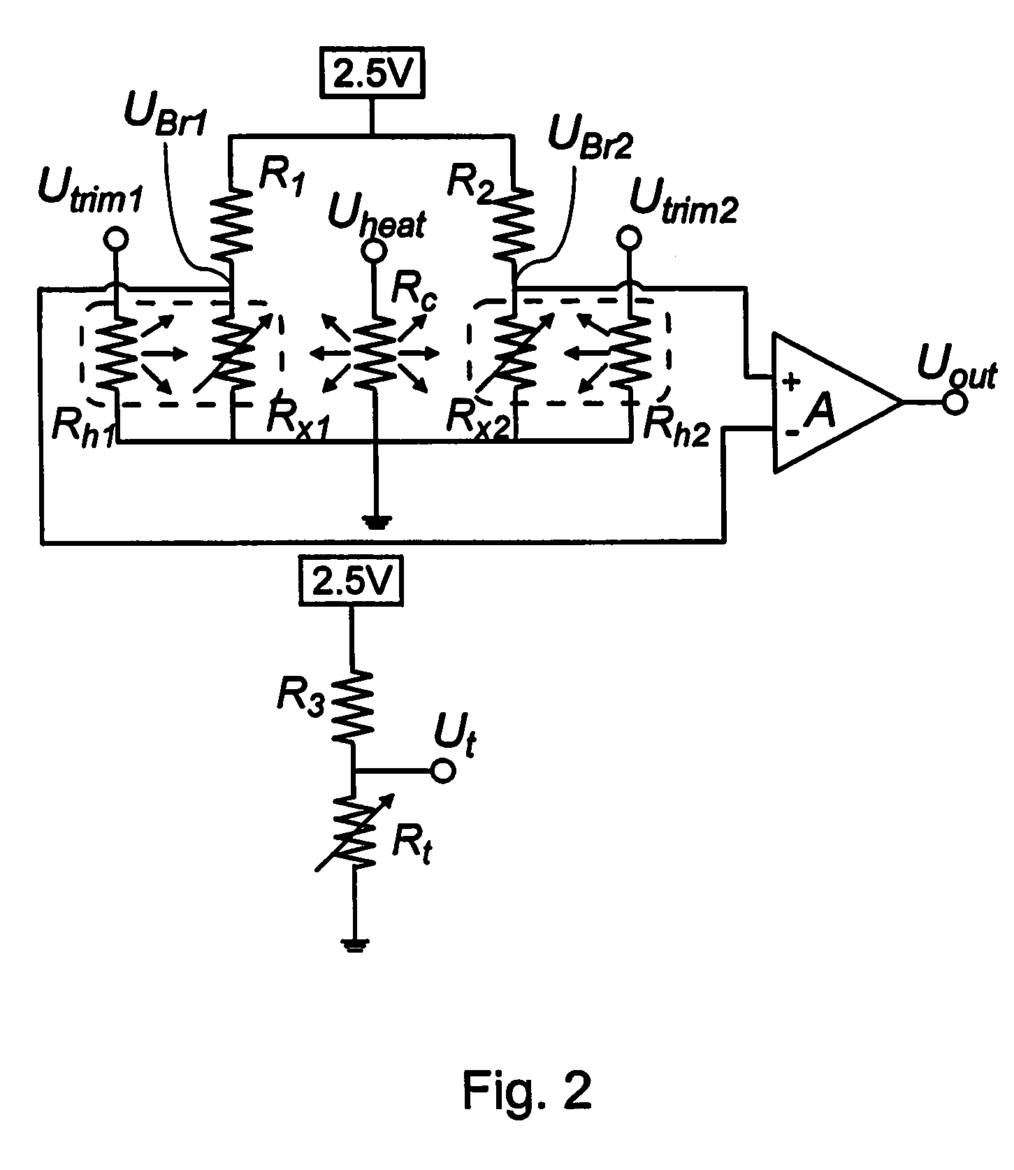
[0052]Throughout the description, the term “output parameter” should be understood as meaning any parameter representing a characteristic of an output signal, such as amplitude, voltage, current, frequency, sensor sensitivity, offset, gain, temperature variation (linearity, non-linearity, or an actual value thereof), etc.

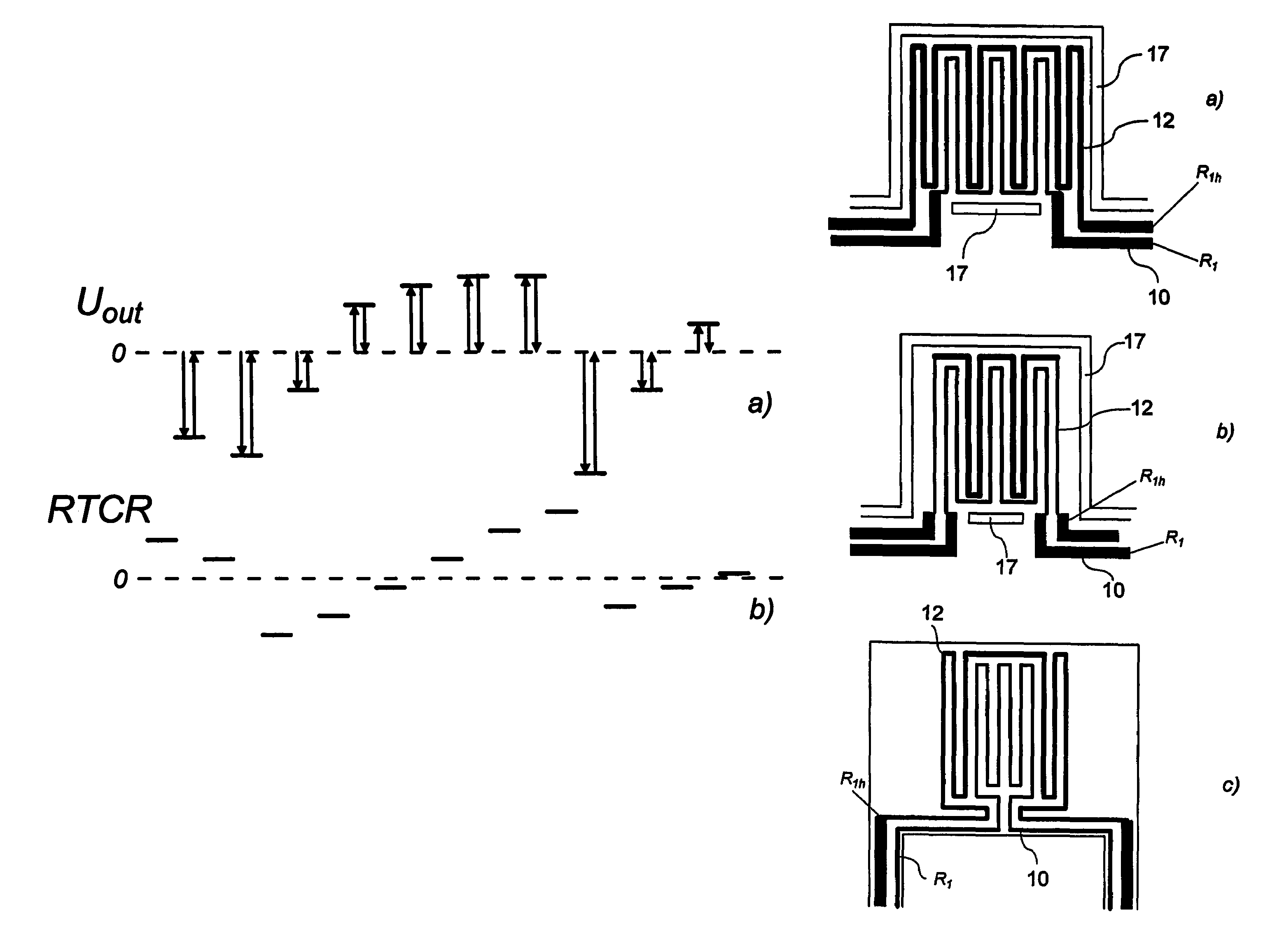
[0053]The term “temperature coefficient of resistance”, and its abbreviations “TCR”, “RTCR”, should be understood in general to include both linear and non-linear coefficients of temperature variation of resistance.

[0054]The term “active semiconductor device” should be understood to include diodes, transistors, metal-oxide-semiconductor devices, field-effect transistors, and any other non-passive electronic component made in a semiconductor wafer or chip.

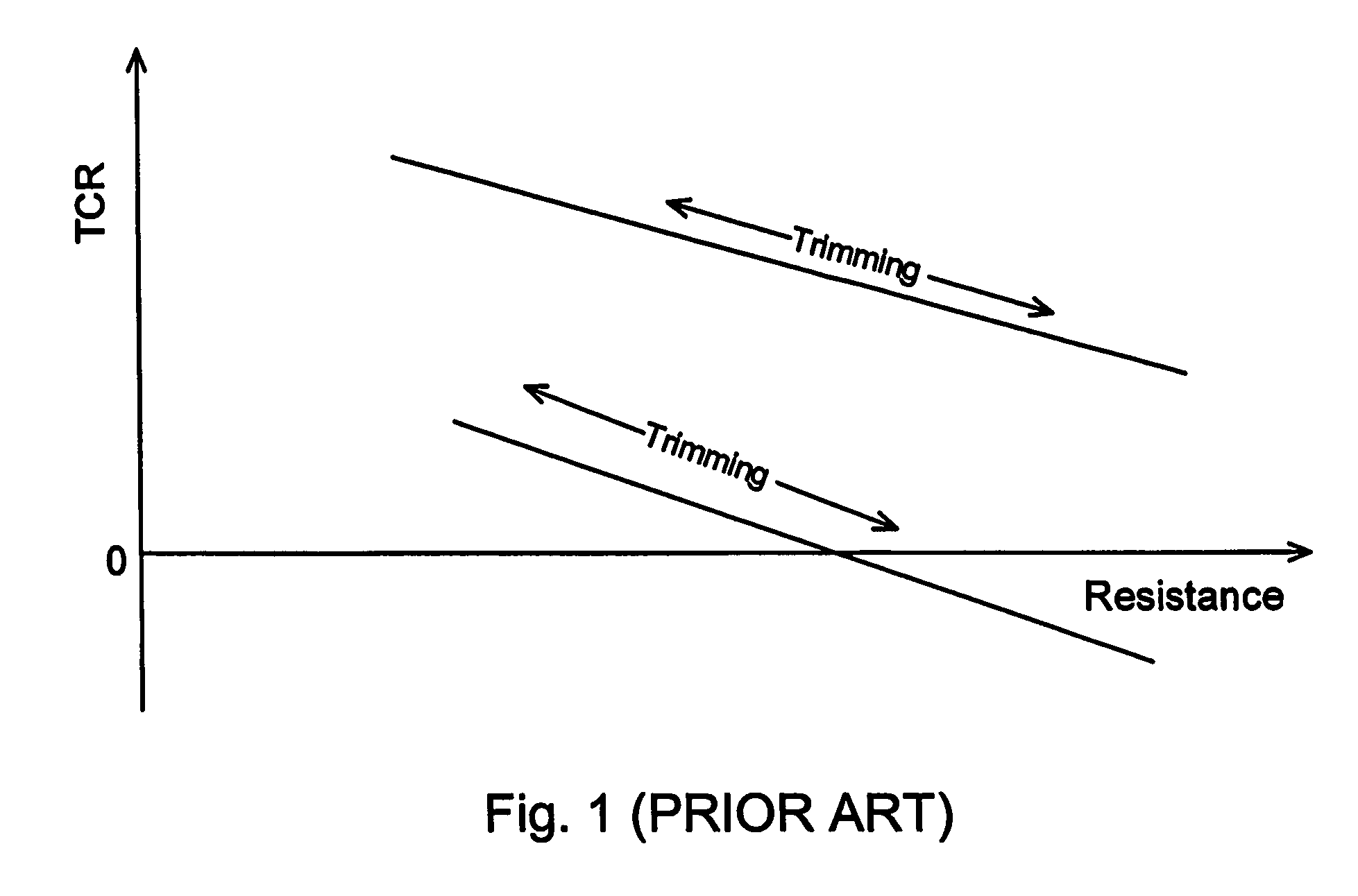
[0055]While the prior art demonstrates that the TCR changes when one trims the resistance, it does not show how to trim the TCR while maintaining a constant resistance value.

[0056]This approach to trim the TCR of th...


PUM

PropertyMeasurementUnit
base-emitter voltageaaaaaaaaaa
circuit voltageaaaaaaaaaa

Abstract

Electro-thermal trimming of thermally-trimmable resistors is used to trim one or more of the plurality of resistors in or associated with an analog electric circuit. The TCR of each of a subset of a plurality of electro-thermally-trimmable resistors can be trimmed independently from the resistance in order to adjust the output parameter of an analog electric circuit without changing other parameters that would be affected by a change in resistance.

Description

CROSS-REFERENCE TO RELATED APPLICATIONS[0001]This application is a national phase entry of international application number PCT / CA2004 / 001030, which claims priority under 35USC§119(e) of U.S. provisional patent application 60 / 486,418 filed on Jul. 14, 2003, which is hereby incorporated by reference.FIELD OF THE INVENTION[0002]The invention relates to adjustment of output parameters of analog circuits. More specifically, it relates to adjusting output parameters of analog circuits by trimming parameters of components within a circuit.BACKGROUND OF THE INVENTION[0003]Calibration of an output parameter of an analog circuit typically depends on adjustment of one or more adjustable components within that circuit. For example, voltage references are a typical precision analog circuit, where adjustment may be required.[0004]In some cases, the adjustable component is a resistor, and the output parameter of the circuit may be directly adjusted by trimming the resistance value of the resistor...

Claims


Application Information

Patent Timeline
Patent Type & Authority Patents(United States)
IPC IPC(8): H01C17/00H01C17/232H01L27/08
CPCH01C17/232H01L27/0802Y10T29/49002Y10T29/49124Y10T29/49082Y10T29/49085Y10T29/49099Y10T29/49117
Inventor GRUDIN, OLEGLANDSBERGER, LESLIE M.FROLOV, GENNADIY
Owner SENSORTECHNICS
Why Eureka
Try Eureka