
Catheters with lubricious linings and methods for making and using them

a technology of lubricating linings and catheters, which is applied in the direction of catheters, synthetic resin layered products, other domestic articles, etc., can solve the problems of difficult to complete the construction of such a catheter, the performance of the catheter is significant, and the inner surface modification, cleaning, etching, etc., to achieve simple and/or readily practicable methods

Active Publication Date: 2009-07-07
CLPH
View PDF59 Cites 29 Cited by
  • Summary
  • Abstract
  • Description
  • Claims
  • Application Information

AI Technical Summary

Benefits of technology

This approach simplifies the manufacturing process, ensures even coating distribution, and maintains the properties of the coated surface, resulting in improved lubricity and reduced manufacturing complexity and costs, enabling more effective delivery of instruments and agents into body lumens.

Problems solved by technology

For such applications, the properties of the inner surface of one or more lumens may significantly impact the performance of the catheter.
Constructing such a catheter, however, is complicated because of the difficulty bonding the inner core to the outer portions of the catheter.
Further, because of the inaccessibility of the inner surface of the lumen of a catheter, mechanical abrasion or modification, cleaning, etching, application of adhesive, or other modifications of the inner surfaces to facilitate bonding are generally difficult to complete.
PE, similar to PTFE, is also difficult to bond to other materials.
In both cases, the manufacturing process is complicated and the materials generally expensive.
Other methods for imparting lubricity to inner surfaces have been tried, for example, vapor deposition of surface coatings such as Paralene; however, this process is also complicated and does not result in optimal lubricity.
Nevertheless, application of coatings to catheter exteriors is subject to process limitations.
Furthermore, application of such coatings to inner surfaces is currently significantly hindered by technical challenges and therefore not practiced generally.
However, inner surfaces, especially small lumens of long catheters, are extremely difficult or impossible to coat because of the difficulty of evenly applying a solution to the inner surface.
Even if the solution could be evenly dispersed over the surface, for example, by addition of surfactants, evaporation of a solvent from inside a long small diameter tube may be slow and irregular, with likely condensation along the way.
Thus, this method of coating an inner surface may not be feasible.
In the case of UV light, it may be difficult to expose an inner surface of a catheter to UV light in order to cross-link the coating, unless the material being coated were transparent to UV light.
Excessive exposure to UV light may also cause material degradation.
Application of heat likewise is not always practicable as it may damage other device components.
With respect to coating outer surfaces, current methods make it relatively difficult to coat discrete sections without masking.
Furthermore, the equipment and fixtures required for coating are generally expensive and processes may be difficult to control.
Due to these challenges, surface modification of inner surfaces, as for example, by application of hydrophilic, anti-anti-thrombotic, anti-biotic, drug-eluting, or other coatings is not easily accomplished, although it would be useful in a variety of applications.
Furthermore, while coating outer surfaces is often performed, various limitations exist in current processes, which may be improved upon.

Method used


Image

  • Catheters with lubricious linings and methods for making and using them
  • Catheters with lubricious linings and methods for making and using them
  • Catheters with lubricious linings and methods for making and using them

Examples


Embodiment Construction

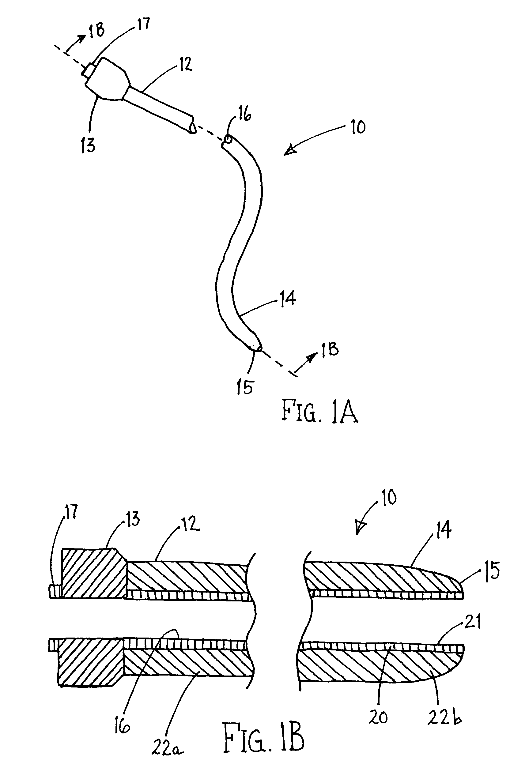
[0043]Turning to the drawings, FIGS. 1A and 1B show an exemplary embodiment of an apparatus 10 for accessing a body lumen (not shown) and / or for delivering one or more fluids, agents, and / or instruments (also not shown) within a body lumen. In exemplary embodiments, the apparatus 10 may be a guide catheter, a procedure catheter, a sheath, an imaging device, or other tubular device sized for introduction into a body lumen, such as a vessel within a patient's vasculature, a passage within a patient's gastrointestinal tract, urogenital tract, reproductive tract, respiratory tract, lymphatic system, and the like, as described further below.

[0044]Generally, the apparatus 10 is an elongate tubular member including a proximal end 12, a distal end 14 sized for insertion into a body lumen, and a lumen 16 extending between the proximal and distal ends 12, 14. Optionally, the apparatus 10 may include one or more additional lumens (not shown), which may be disposed concentrically around or side...


PUM

PropertyMeasurementUnit
lengthaaaaaaaaaa
lengthaaaaaaaaaa
lengthaaaaaaaaaa

Abstract

Coated devices for introduction into bodies and methods for making and using them are provided, such as delivery sheaths, guidewire lumen cores, and elongate leads. In one embodiment, a tubular device includes a proximal end, a distal end sized for introduction into a body lumen, and a lumen extending between the proximal and distal ends. The tubular device includes a relatively thin inner polyurethane liner including a coating on an inner surface thereof, e.g., providing a lubricious and / or hydrophilic lumen, and an outer layer surrounding the liner. In another embodiment, a lead is provided that includes a proximal end, a distal end, and at least one electrode on the distal end. A polyurethane cover surrounds at least a portion of an outer surface of the lead that include a coating, e.g., including a lubricious and / or hydrophilic material. Optionally, the cover may be removable from around the lead body.

Description

[0001]This application claims benefit of provisional application Ser. No. 60 / 723,300, filed Oct. 4, 2005, the entire disclosure of which is expressly incorporated herein by reference.FIELD OF THE INVENTION[0002]The present invention relates generally to devices for providing access into body lumens and, more particularly, to catheters, sheaths, and other tubular devices with lubricious linings and methods for making and using them.BACKGROUND[0003]Catheters are elongate tubular devices sized for introduction into body passages and cavities of a patient, such as a patient's vascular system, gastrointestinal system, abdominal cavity, and the like. A catheter may include one or more lumens intended for passing various other devices, agents, and / or fluids into a body lumen or cavity accessed by the catheter. For such applications, the properties of the inner surface of one or more lumens may significantly impact the performance of the catheter. In particular, the lubricity of the inner s...

Claims


Application Information

Patent Timeline
Patent Type & Authority Patents(United States)
IPC IPC(8): B29C63/10A61M25/00A61M5/32B29C47/00B29C53/00B29C53/78B29C65/00B32B27/00B32B37/00B29C48/09B29C48/10B29C48/11B29C48/13B29C48/151B29C48/21
CPCA61L29/085A61M25/0009B29C47/0028B29C61/006B29D23/001B32B1/08B32B5/028B32B27/08B32B27/12B32B27/285B32B27/32B32B27/34B32B27/40A61L29/14C08L75/04Y10T156/1038A61M25/0045A61M2025/0046B29C47/0026B29C47/0033B29C47/0038B29C53/40B29C65/00B29C66/1122B29C66/43B29C67/0018B29C69/001B29C2793/009B29L2031/602B29L2031/753B29L2031/7542B32B2255/10B32B2255/24B32B2255/26B32B2535/00B29C47/065B29C47/021B29C47/0023B29C66/49B29C66/432B29C66/4322B29C66/1142B29C66/131B29C66/52272B29C48/09B29C48/10B29C48/11B29C48/13B29C48/001B29C48/151B29C48/21
Inventor LEEFLANG, STEPHEN A.EVERSULL, CHRISTIAN S.MOURLAS, NICHOLAS J.VENTURA, CHRISTINE P.
Owner CLPH
Learn More