Use of beacons in a WDM communication system

a communication system and wavelength division multiplexing technology, applied in multiplex communication, optics, instruments, etc., can solve the problems of difficult phase lock to the carrier wavelength, complex task of providing multiple phase-locked lo signals for multiple wavelengths, and complicating the use of homodyne psk in prior-art wdm systems. , to achieve the effect of simple phase-lock circuitry

Active Publication Date: 2009-07-14
ALCATEL-LUCENT USA INC
View PDF7 Cites 22 Cited by
  • Summary
  • Abstract
  • Description
  • Claims
  • Application Information

AI Technical Summary

Benefits of technology

[0010]Advantageously, having, at a transmitter and a receiver, two OFCSs that are phase-locked to one another enables the use of PSK modulation and homodyne detection while employing relatively simple phase-lock circuitry. For example, a phase-lock loop that locks the phases of the comb lines generated by the receiver's OFCS to the respective beacon lines of the received WDM signal also produces a substantial phase lock between one or more additional comb lines of the receiver's OFCS and the respective one or more non-beacon components of the WDM signal. As a result, these non-beacon components of the WDM signal can be processed at the receiver using homodyne detection without employing any additional phase-lock loops.

Problems solved by technology

One problem with the use of homodyne PSK is that the homodyne detection of each modulated signal utilizes a LO signal that is phase-locked to the carrier wavelength of that modulated signal.
However, at the receiver, a phase-lock to the carrier wavelength is relatively difficult to achieve because the PSK causes pseudo-random phase variation in the received signal.
Also, the task of providing multiple phase-locked LO signals for multiple wavelengths further complicates the use of homodyne PSK in prior-art WDM systems.

Method used


Image

  • Use of beacons in a WDM communication system
  • Use of beacons in a WDM communication system
  • Use of beacons in a WDM communication system

Examples


Embodiment Construction

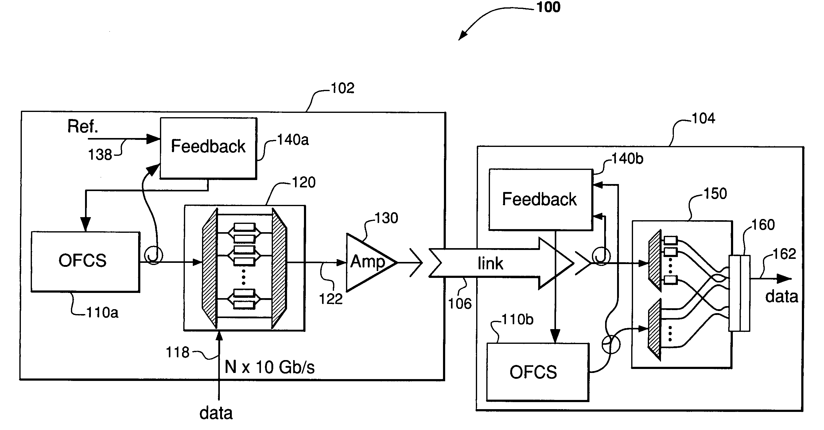
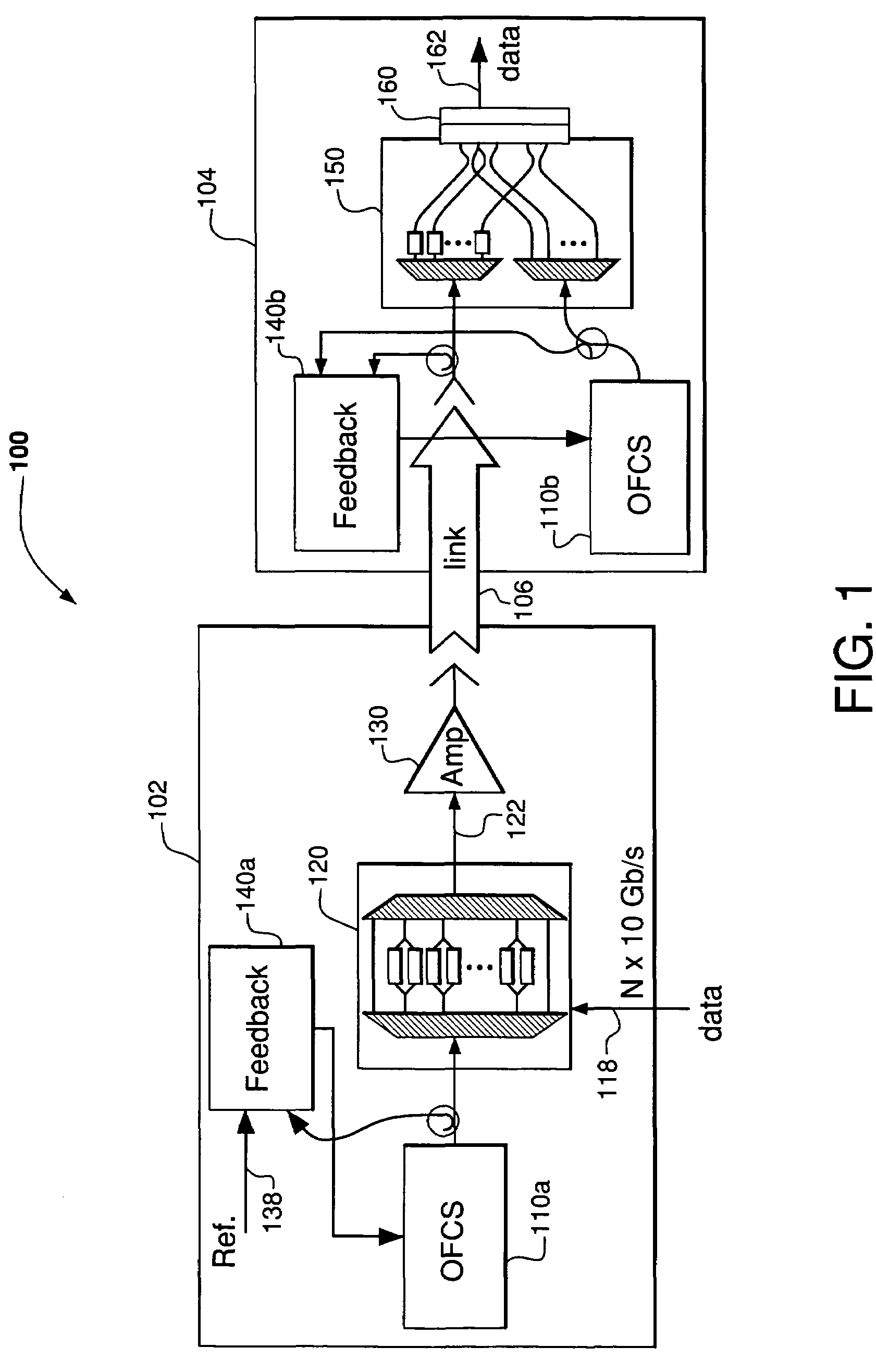
[0021]FIG. 1 shows a WDM communication system 100 according to one embodiment of the invention. System 100 has a WDM transmitter 102 and a WDM receiver 104 coupled via an optical communication link 106. Transmitter 102 has an optical-frequency comb source (OFCS) 110a that is adapted to generate a plurality of frequency (wavelength) components. In one configuration, the frequency components can be substantially uniformly spaced. In another configuration, some of the frequency components can be suppressed or filtered out to create a plurality of non-uniformly spaced frequency components. Hereafter, a plurality of frequency components generated by an OFCS analogous to OFCS 110a is referred to as a “frequency comb” and each individual frequency component of a frequency comb is referred to as a “comb line.”

[0022]An optical modulator 120 coupled to OFCS 110a is configured to modulate some or all of the comb lines generated by that OFCS with data that are provided by a data stream 118. Mod...


PUM

PropertyMeasurementUnit
frequencyaaaaaaaaaa
phaseaaaaaaaaaa
lengthaaaaaaaaaa

Abstract

A WDM communication system having two optical-frequency comb sources (OFCSs) that are substantially phase-locked to one another, with one of these OFCSs used at a transmitter to produce a WDM communication signal and the other OFCS used at a receiver to produce multiple local-oscillator signals suitable for homodyne detection of the WDM communication signal received from the transmitter. In one embodiment, the transmitter has (i) a first OFCS adapted to generate a first frequency comb and (ii) an optical modulator adapted to use the first frequency comb to generate a WDM communication signal having at least two beacon lines for transmission to the receiver. The receiver has a second OFCS adapted to produce a second frequency comb having the beacon frequencies, with the phases of the corresponding comb lines being locked to the phases of the beacon lines of the received WDM signal.

Description

CROSS-REFERENCE TO RELATED APPLICATIONS[0001]The subject matter of this application is related to that of U.S. patent application Ser. No. 11 / 333,105, filed on the same date as the present application and now issued as U.S. Pat. No. 7,123,402, which is incorporated herein by reference in its entirety.BACKGROUND OF THE INVENTION[0002]1. Field of the Invention[0003]The present invention relates to optical communication equipment and, more specifically, to equipment for optical wavelength division multiplexing (WDM) communication systems.[0004]2. Description of the Related Art[0005]An optical WDM communication system is designed to use optical signals having multiple carrier wavelengths (frequencies). Each carrier wavelength can be individually modulated with data and combined with other modulated wavelengths. The resulting optical WDM signal is transmitted over an optical communication link, e.g., an optical fiber, from a transmitter to a receiver, where the modulated wavelengths are ...

Claims


Application Information

Patent Timeline
Patent Type & Authority Patents(United States)
IPC IPC(8): H01S3/13H04B10/00H04B10/04H04B10/12G02F2/02H01S3/098
CPCH04B10/60H04B10/63H04J14/025H04J14/0246H04J14/0279H04J14/0227
Inventor DOERR, CHRISTOPHER RICHARDWINZER, PETER J.
Owner ALCATEL-LUCENT USA INC
Why Eureka
Try Eureka