
Transceiver module and integrated circuit with clock and data recovery clock diplexing

a transceiver module and integrated circuit technology, applied in the field of on-chip clock and data recovery in a transceiver module, to achieve the effect of reducing bit errors

Active Publication Date: 2009-07-14
II VI DELAWARE INC
View PDF181 Cites 27 Cited by
  • Summary
  • Abstract
  • Description
  • Claims
  • Application Information

AI Technical Summary

Benefits of technology

The patent describes an integrated circuit that can handle data streams and clock signals. The circuit has a feature called an eye opening circuit that can adjust the timing of the data stream to reduce errors. The circuit can also selectively retime or bypass the data stream using the clock signal. This allows for the use of retiming circuits on high-speed communication circuits to reduce errors. Overall, the invention provides a more flexible and efficient way to handle data.

Problems solved by technology

Advantageously, some embodiments allow for integrated circuits which ordinarily would not allow for clock signals to accommodate clock signals for retiming and eye opening functionality.

Method used


Image

  • Transceiver module and integrated circuit with clock and data recovery clock diplexing
  • Transceiver module and integrated circuit with clock and data recovery clock diplexing
  • Transceiver module and integrated circuit with clock and data recovery clock diplexing

Examples


first embodiment

[0097]FIG. 20 illustrates an eye opener having an equalizer. The data path of eye opener 2100 comprises an equalizer 2120, which receives data from a buffer 2105a and outputs data to a buffer 2105b. The buffer 2105a receives data from a receiver and the buffer 2105b sends data to a host. In another embodiment, the buffer 2105a receives data from the host and the buffer 2105b sends data to a transmitter. In one embodiment the eye opener 2100 conditions a signal in bypass mode.

[0098]The equalizer 2120 resets the data path's jitter budget by reshaping and retiming the data to remove channel noise from sources such as inter-symbol interference. The equalizer 2120 is coupled to receive signals representing coefficients from a coefficient module 2110 and a clock signal from a CDR 2130. The equalizer 2120 is preferably an adaptive equalizer that adapts to channel conditions such as changing temperature, but in other embodiments, the equalizer 2120 may be a passive equalizer. Other embodime...

second embodiment

[0101]FIG. 21 illustrates an eye opener having an equalizer. In this embodiment, the data path of eye opener 2180 comprises an equalizer 2150 in series with a CDR 2160 coupled with an RT 2170. The equalizer 2150 receives data from the buffer 2155a and the RT 2170 outputs data to the buffer 2155b. The CDR 2160 and equalizer 2150 may be disposed on separate chips or an integrated circuit. One advantage of this embodiment, is that the signal is conditioned by both the equalizer 2150 and CDR 2160, leading to a lower bit error rate.

[0102]In contrast to the embodiment of FIG. 21, the equalizer 2150 preferably reshapes and outputs an analog signal by removing channel effects. The equalizer 2150 receives a clock signal from the CDR 2160 to clock the equalizer's digital components.

[0103]The CDR 2160 and R T 2170 retime and reshape the equalized data. The RT 2170 receives a clock signal recovered by the CDR 2160. The CDR 2160 and RT 2170 may comprise the variations discussed herein.

[0104]In a...


PUM


Abstract

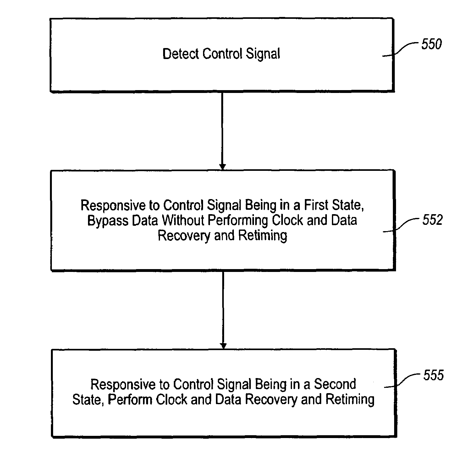
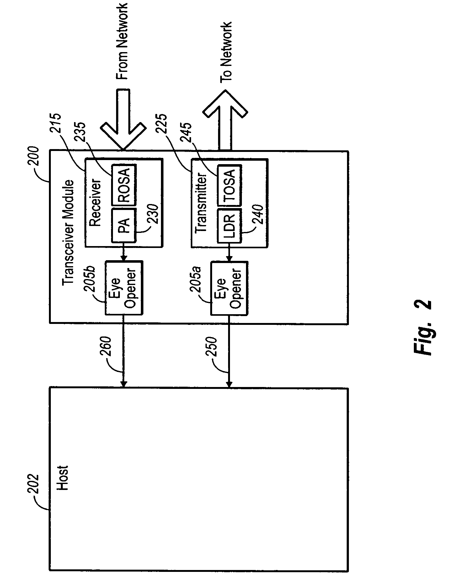
An integrated circuit. The integrated circuit is usable in a transceiver module. The integrated circuit includes an input port that is configured to receive a data stream. A clock port on the integrated circuit is configured to receive a reference clock diplexed with another signal or voltage used by the integrated circuit. An eye opening circuit is connected to the input port and clock. The eye opening circuit is configured to retime the data stream received at the input port. An output port is connected to the eye opening circuits The output port is configured to transmit a retimed signal from the eye opening circuit to a device external to the integrated circuit. A bypass circuit is connected to the input port and the output port. The bypass circuit may selectively bypass the eye opening circuit.

Description

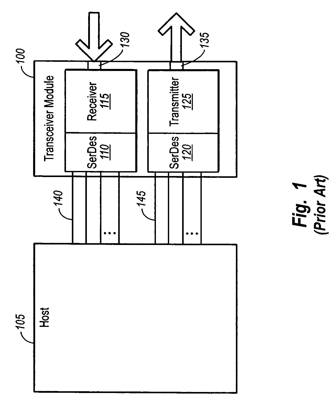
CROSS-REFERENCE TO RELATED APPLICATIONS[0001]This application is a continuation in part of U.S. patent application Ser. No. 10 / 629,301, “Transceiver Module and Integrated Circuit With Multi-Rate Eye Openers and Bypass”, filed Jul. 28, 2003, which is a divisional of U.S. patent application Ser. No. 10 / 420,027, “Transceiver Module and Integrated Circuit With Dual Eye Openers,” filed Apr. 17, 2003, now U.S. Pat. No. 7,486,894 which claims the benefit of U.S. Provisional Patent Application Ser. No. 60 / 410,509, filed Sep. 13, 2002 and which also claims the benefit of U.S. Provisional Patent Application Ser. No. 60 / 391,877, filed Jun. 25, 2002. The foregoing patent applications are incorporated herein by reference in their entirety.BACKGROUND OF THE INVENTION[0002]1. The Field of the Invention[0003]The present invention relates generally to ensuring data integrity within a networking box, and more particularly, to on-chip clock and data recovery in a transceiver module.[0004]2. Background...

Claims


Application Information

Patent Timeline
Patent Type & Authority Patents(United States)
IPC IPC(8): H04B1/40H04L1/00H04L1/20H04L1/24
CPCH04L1/243H04L1/205
Inventor HOFMEISTER, RUDOLF J.ARONSON, LEWIS B.
Owner II VI DELAWARE INC
Learn More