
Tunable light source apparatus, and adjustment method and control program of the same

a light source and tunable technology, applied in the direction of instruments, semiconductor lasers, optical elements, etc., can solve the problems of loss accumulation, fluctuation and deviation of laser oscillation wavelengths, unexpected wavelength skipping etc.,

Inactive Publication Date: 2009-07-21
NEC CORP
View PDF26 Cites 25 Cited by
  • Summary
  • Abstract
  • Description
  • Claims
  • Application Information

AI Technical Summary

Benefits of technology

The invention is about a tunable light source apparatus that includes a multiple-optical resonator. The central frequencies of the resonators are aligned with the set frequency to achieve optimal mode gain difference, and the output laser light is locked within a range of about 1 GHz from the set frequency. The apparatus includes an optical resonator filter with multiple optical resonators, a light supply device, a tunable device for changing the resonance wavelength, two light detection devices, and a control unit for controlling the tunable device based on the detected lights. The control method involves detecting the output light from the optical resonator filter and the light that is deviated from the resonator path, and adjusting the tunable device accordingly. The technical effect of the invention is to provide a reliable and efficient way to adjust the wavelength of a light source.

Problems solved by technology

However, in the multi-purpose tunable light source apparatus, the laser oscillation wavelength fluctuates and deviates from the ITU-Grid due to change in outside temperature and variation in refractive index of the light waveguide portion.
Disadvantages such as unexpected wavelength skipping etc. arise unless the assumed mode gain difference is obtained.
If the average number of turns increases, the propagation loss accumulates and the insertion loss increases as it passes through the ring resonator that many times, and thus a trade off state such that the output of the light source becomes difficult to be obtained arises.

Method used


Image

  • Tunable light source apparatus, and adjustment method and control program of the same
  • Tunable light source apparatus, and adjustment method and control program of the same
  • Tunable light source apparatus, and adjustment method and control program of the same

Examples


Embodiment Construction

[0030]One exemplary embodiment of the present invention will now be described with reference to the drawings.

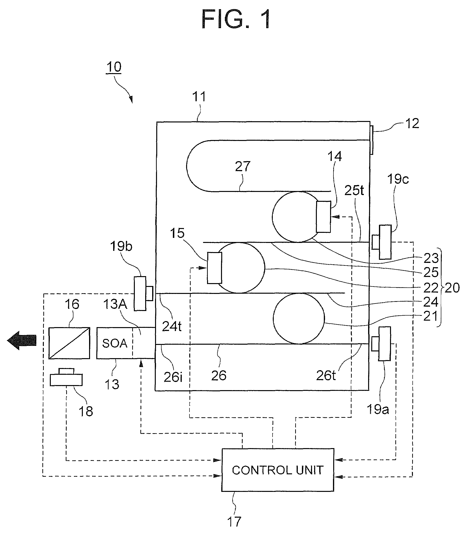
[0031]FIG. 1 is a plan view showing a tunable light source apparatus 10 of the exemplary embodiment.

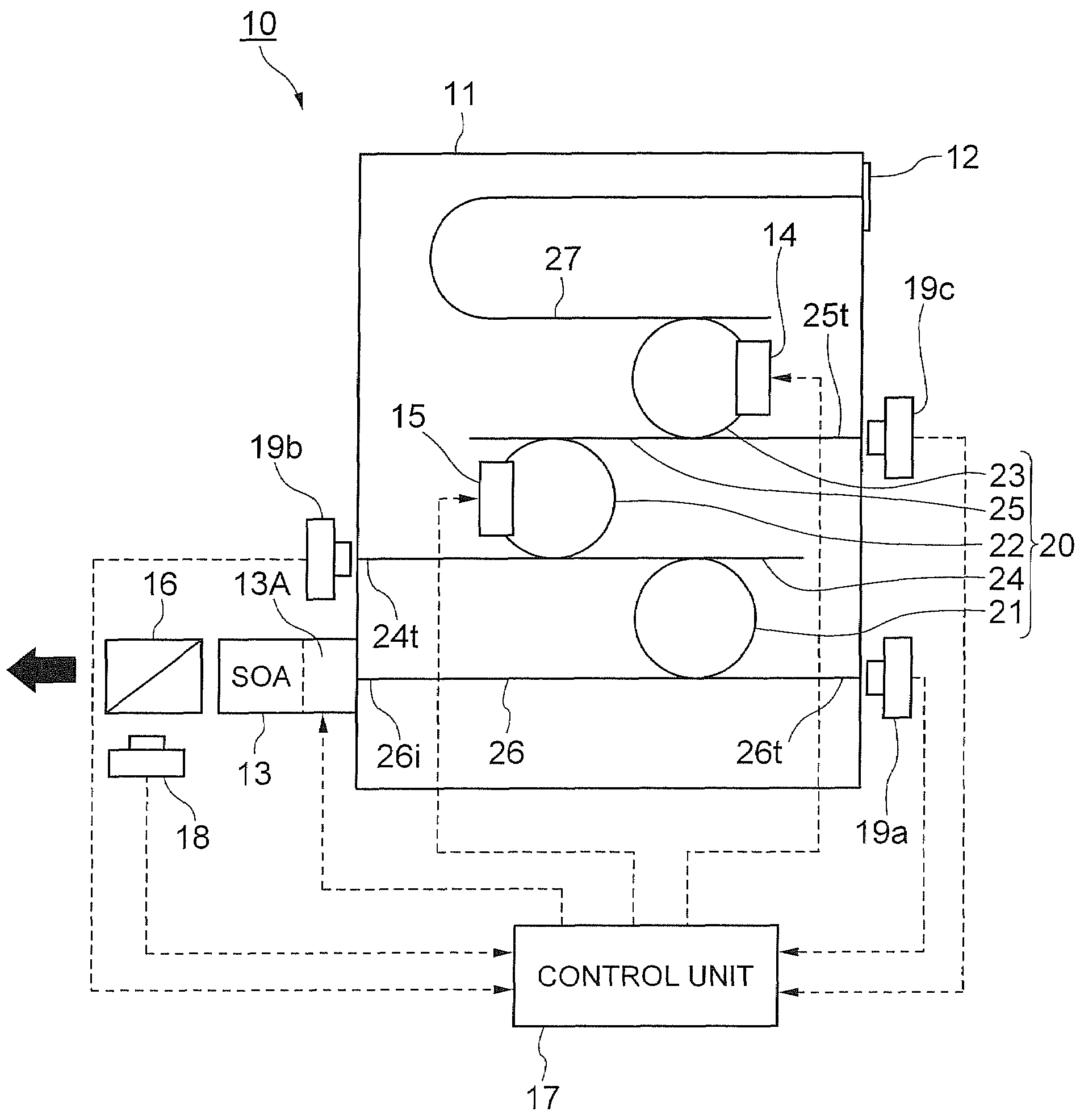
[0032]As shown in FIG. 1, the tunable light source apparatus 10 of the exemplary embodiment includes an optical resonator filter 11, or a PLC (Planar Lightwave Circuit), configured by forming a multiple-optical resonator 20 in which ring resonators 21, 22, and 23 with different light path lengths are connected via waveguides 24, 25, an input / output side optical waveguide 26 on the side for inputting / outputting the laser light, and a reflection side optical waveguide 27 including a light reflection film 12 arranged on one end; and an SOA (Semiconductor Optical Amplifier) 13 serving as a light supply device connected to a light input / output port 26i of the optical resonator filter 11.

[0033]Furthermore, the tunable light source apparatus 10 of the exemplary embodiment is configure...


PUM


Abstract

The present invention aims to provide a tuning light source apparatus including a multiple-optical resonator, where the resonance frequencies of the respective optical resonators in a multiple-optical resonator are exactly coincided with the set frequency, and the frequency of the output laser beam is locked within a range of about 1 GHz from the set frequency. Current is flowed to TO phase shifters based on lights detected by light receiving elements, and the resonance wavelengths of resonators are adjusted in an aim of obtaining a state in which an intensity of an oscillation light becomes a maximum and at the same time an intensity of a light from a through port becomes a minimum.

Description

CROSS-REFERENCE TO RELATED APPLICATION[0001]This application is based upon and claims the benefit of priority from Japanese patent application No. 2007-112642, filed on Apr. 23, 2007, the disclosure of which is incorporated herein in its entirety by reference.BACKGROUND OF THE INVENTION[0002]1. Field of the Invention[0003]The present invention relates to tunable light source apparatuses used in optical fiber communication, light source wavelength adjustment methods, and light source wavelength adjustment programs, in particular, to a tunable light source apparatus used in an optical communication of WDM (Wavelength Division Multiplexing) transmission system, a light source wavelength adjustment method, and a light source wavelength adjustment program.[0004]2. Related Art[0005]Recently, in the field of optical communication, the WDM transmission system of converting a plurality of data signals to light signals of different wavelengths, and multiplexing the plurality of light signals ...

Claims


Application Information

Patent Timeline
Patent Type & Authority Patents(United States)
IPC IPC(8): G02B6/26H01S3/08
CPCH01S5/141H01S5/0687H01S5/1032H01S5/065H01S5/028H01S5/0287H01S5/06246H01S5/0656H01S5/142
Inventor SUZUKI, KOUICHI
Owner NEC CORP
Learn More