Highly conductive nano-scaled graphene plate nanocomposites

a graphene plate, nano-scale technology, applied in the direction of non-metal conductors, conductors, electrochemical generators, etc., can solve the problems of high material cost, high material cost, and high cost of carbon nanotube-reinforced composite materials, and achieve high bulk electrical conductivity, high thickness-direction conductivity, and high conductivity.

Active Publication Date: 2009-07-28
GLOBAL GRAPHENE GRP INC
View PDF13 Cites 67 Cited by
  • Summary
  • Abstract
  • Description
  • Claims
  • Application Information

AI Technical Summary

Problems solved by technology

However, there are several drawbacks associated with carbon nanotube-reinforced composites.
First, CNTs are known to be extremely expensive due to the low yield and low production and purification rates commonly associated with the current CNT preparation processes.
The high material costs have significantly hindered the widespread application of CNTs.
However, CNTs tend to form a tangled mess resembling a hairball, which is difficult to work with.
This and other difficulties have limited efforts toward realizing a composite material containing well-dispersed CNTs with desired orientations.
In the field of composites, micron-sized fillers often result in the formation of micron-sized defects, hence compromising the composite strength.
For fully separated, individual plates dispersed in a polymer, the viscosity is typically too high to be processable by mass production techniques such as extrusion, injection molding, or even compression molding (hot press molding).
However, at these threshold EGF loadings, the electrical conductivity of the resulting composite, typically in the range of 10−5-10−1 S / cm, is still too low for many useful engineering applications.
Conventional EGF composites with a high EGF loading either can not be formed into thin composite plate, can not be molded with mass production techniques, or are simply not processable into useful products.
The composite in this case was formed by “intercalation and in situ polymerization.” Again, these porous structures led to weak composites.
This process is typically slow and, hence, expensive.
A vast majority of the existing polymers cannot be prepared in this manner.
13,14], but residual solvent can be problematic.
No non-polymeric matrices have hitherto been reported for use in making nanocomposites containing separated EG flakes that are of good structural integrity.

Method used


Image

  • Highly conductive nano-scaled graphene plate nanocomposites
  • Highly conductive nano-scaled graphene plate nanocomposites
  • Highly conductive nano-scaled graphene plate nanocomposites

Examples


Embodiment Construction

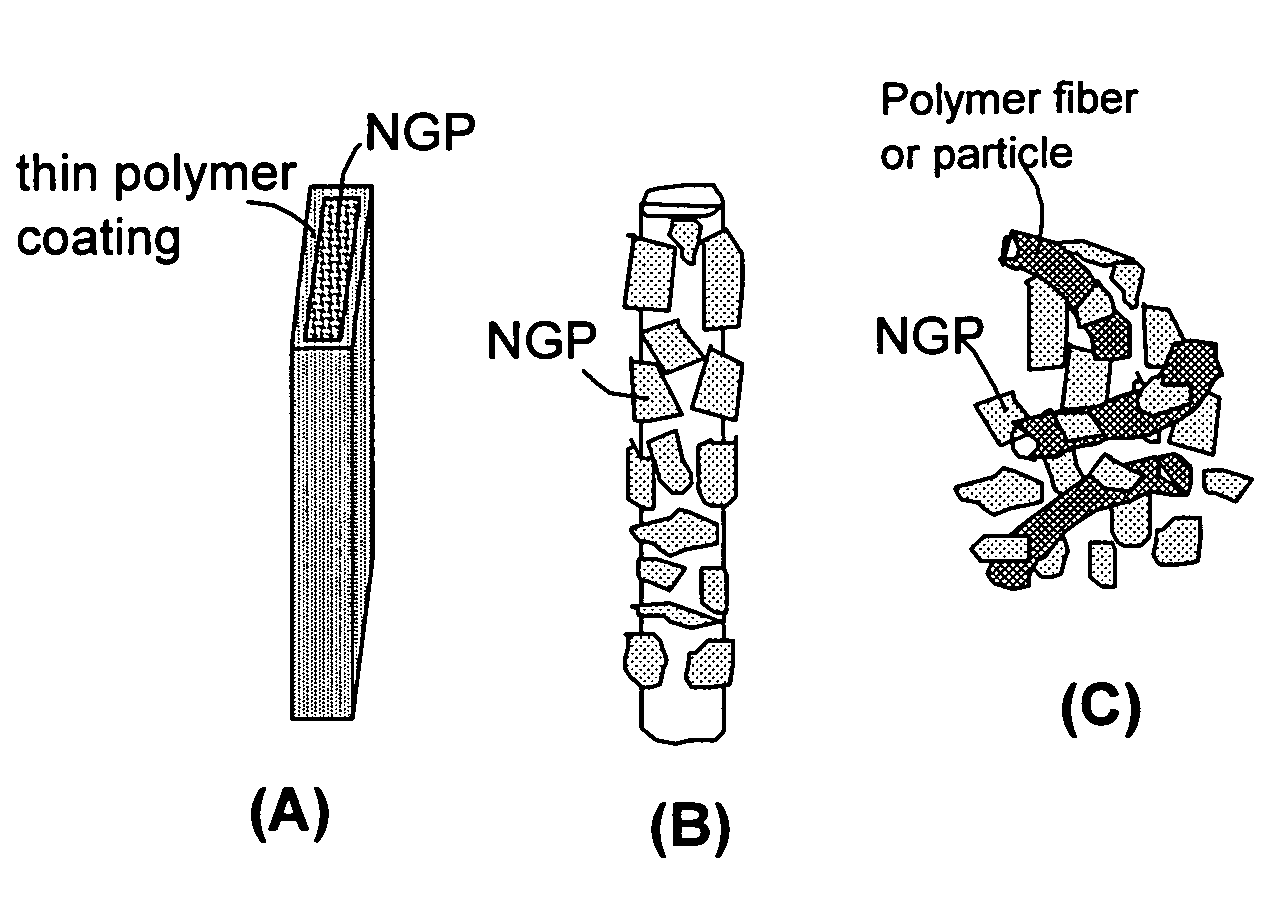
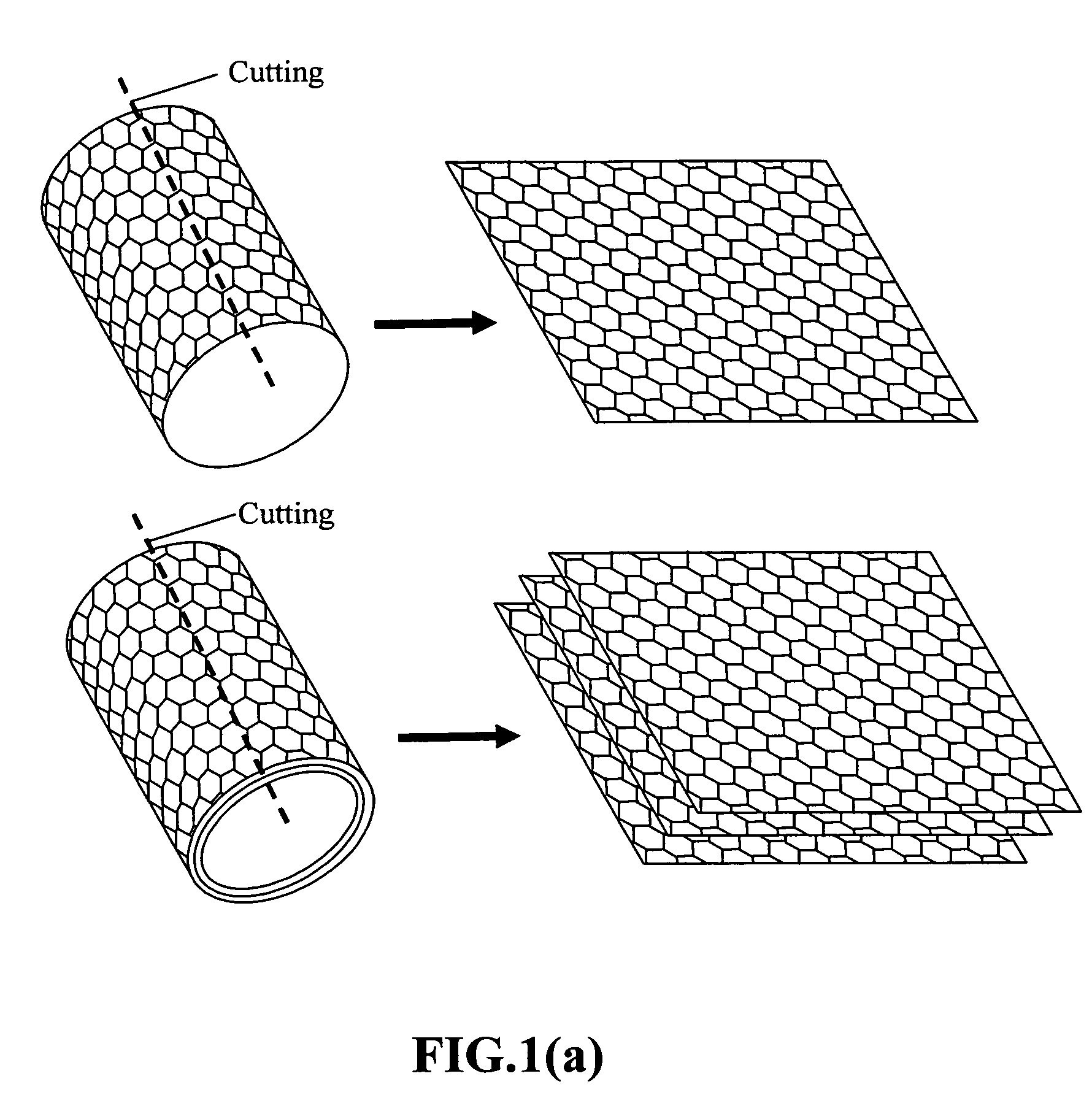
[0063]The present invention may be understood more readily by reference to the following detailed description of the invention taken in connection with the accompanying drawing figures, which form a part of this disclosure. It is to be understood that this invention is not limited to the specific devices, methods, conditions or parameters described and / or shown herein, and that the terminology used herein is for the purpose of describing particular embodiments by way of example only and is not intended to be limiting of the claimed invention. Also, as used in the specification including the appended claims, the singular forms “a,”“an,” and “the” include the plural, and reference to a particular numerical value includes at least that particular value, unless the context clearly dictates otherwise. Ranges may be expressed herein as from “about” or “approximately” one particular value and / or to “about” or “approximately” another particular value. When such a range is expressed, another...


PUM

PropertyMeasurementUnit
thicknessaaaaaaaaaa
areal conductivityaaaaaaaaaa
diameteraaaaaaaaaa

Abstract

Disclosed is a nano-composite material comprising fully separated nano-scaled graphene platelets (NGPs) dispersed in a matrix material, wherein each of the platelets comprises a sheet of graphite plane or multiple sheets of graphite plane and has a thickness no greater than 100 nm and the platelets have an average length, width, or diameter no greater than 500 nm. The graphene plates are present in an amount no less than 15% by weight based on the total weight of the platelets and the matrix material combined. Typically, the nanocomposite is electrically conductive with a bulk conductivity no less than 10 S / cm and more typically no less than 100 S / cm. Highly conductive NGP nanocomposites are particularly useful for fuel cell flow field plate (bipolar plate) and battery electrode applications. Nanocomposites with high NGP proportions can be used in automotive friction plates and aircraft brake components.

Description

[0001]This invention is based on the results of a research project sponsored by the US DOE SBIR Program. The US government has certain rights on this invention.FIELD OF THE INVENTION[0002]The present invention relates generally to the field of nanocomposite materials, and more particularly to nano-graphene plate-reinforced composite materials (NGP nanocomposites) and products such as fuel cell bipolar plates and battery electrodes made of these nanocomposites.BACKGROUND OF THE INVENTION[0003]Carbon nanotubes (CNT) are nanometer-scale sized tube-shaped molecules having the structure of a graphite molecule rolled into a rube. A nanotube can be single-walled or multi-walled, dependent upon conditions of preparation. Carbon nanotubes typically are electrically conductive and mechanically strong and stiff along their length. Nanotubes typically also have a relatively high aspect ratio (length / diameter ratio). Due to these properties, the use of CNTs as reinforcements in composite materia...

Claims


Application Information

Patent Timeline
Patent Type & Authority Patents(United States)
IPC IPC(8): H01B1/00H01B1/20
CPCB82Y30/00H01B1/24H01M8/0223H01M8/0213H01M4/02Y02E60/50H01M8/0215H01M8/0221Y10S977/70Y10S977/755Y10S977/773Y10S977/778Y10S977/783
Inventor SONG, LULUGUO, JIUSHENGZHAMU, ARUNAJANG, BOR Z.
Owner GLOBAL GRAPHENE GRP INC
Why Eureka
Try Eureka