System and method for downhole telemetry

a technology of telemetry and downhole, applied in the field of system and method for downhole telemetry, can solve the problems of tripping a drill string, requiring the removal of the drill assembly, and affecting the etc., and achieves the effect of relatively slow actual rate of data transmission

Active Publication Date: 2009-08-11
MOSTAR DIRECTIONAL TECH
View PDF69 Cites 87 Cited by
  • Summary
  • Abstract
  • Description
  • Claims
  • Application Information

AI Technical Summary

Problems solved by technology

A paramount problem with obtaining downhole measurements via a wireline is that the drilling assembly must be removed or “tripped” from the wellbore before the probe can be lowered into the wellbore to obtain the measurements.
Tripping a drill string is typically time consuming and thus costly, especially when a substantial portion of the wellbore has been drilled.
The actual rate of data transmission, however, is relatively slow due to factors such as pulse spreading, distortion, attenuation, modulation rate limitations, and other disruptive forces such as ambient noise in the transmission channel.
Although the drill string acts as part of the conductive path, system losses are almost always dominated by conduction losses within the earth which, as noted above, also carries the electromagnetic radiation.
However, EM systems may be affected by distortion or signal dampening due to geologic formations such as dry coal seams, anhydrite, and salt domes.
However, if a signal is lost due to the presence of the aforementioned geological conditions, the rig must be shut down and the drill string tripped to swap the EM system with an alternative system such as a mud-pulse system which, although slower, is generally more reliable.
The inherent downtime while tripping the drill string can often be considerable and thus undesirable.
In general, one problem associated with mud-pulse telemetry is that it can only be used during the drilling operation as it relies on the flow of mud in the mud-column.

Method used


Image

  • System and method for downhole telemetry
  • System and method for downhole telemetry
  • System and method for downhole telemetry

Examples


Embodiment Construction

Drilling Environment

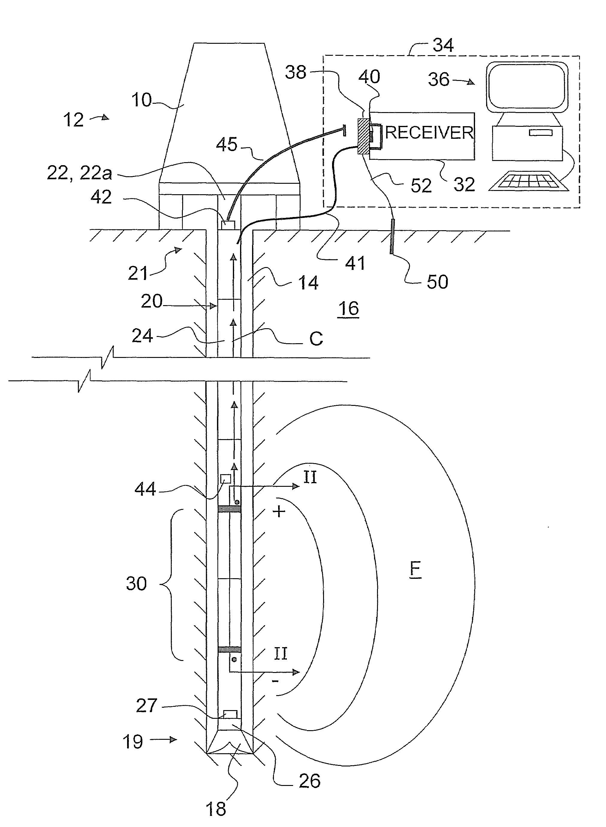
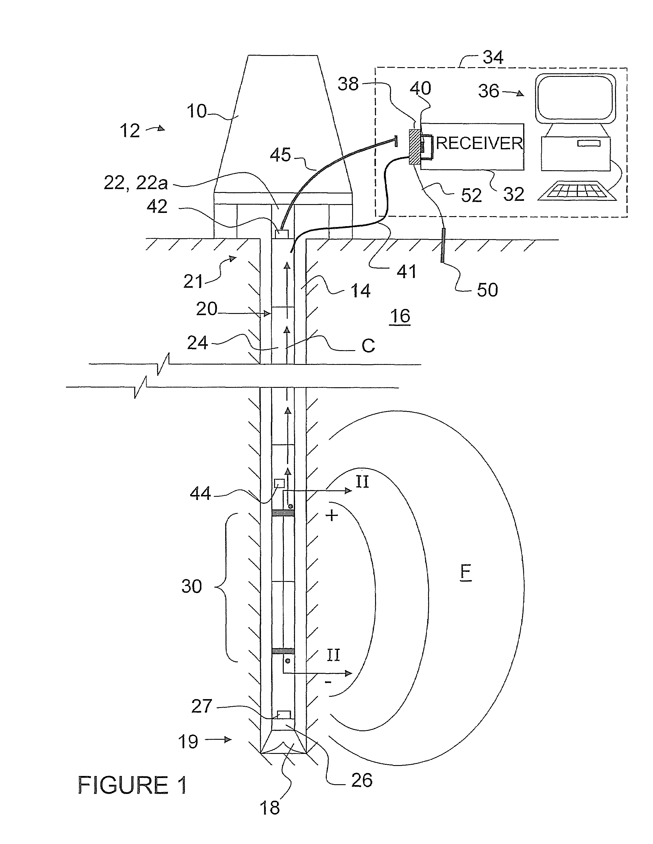
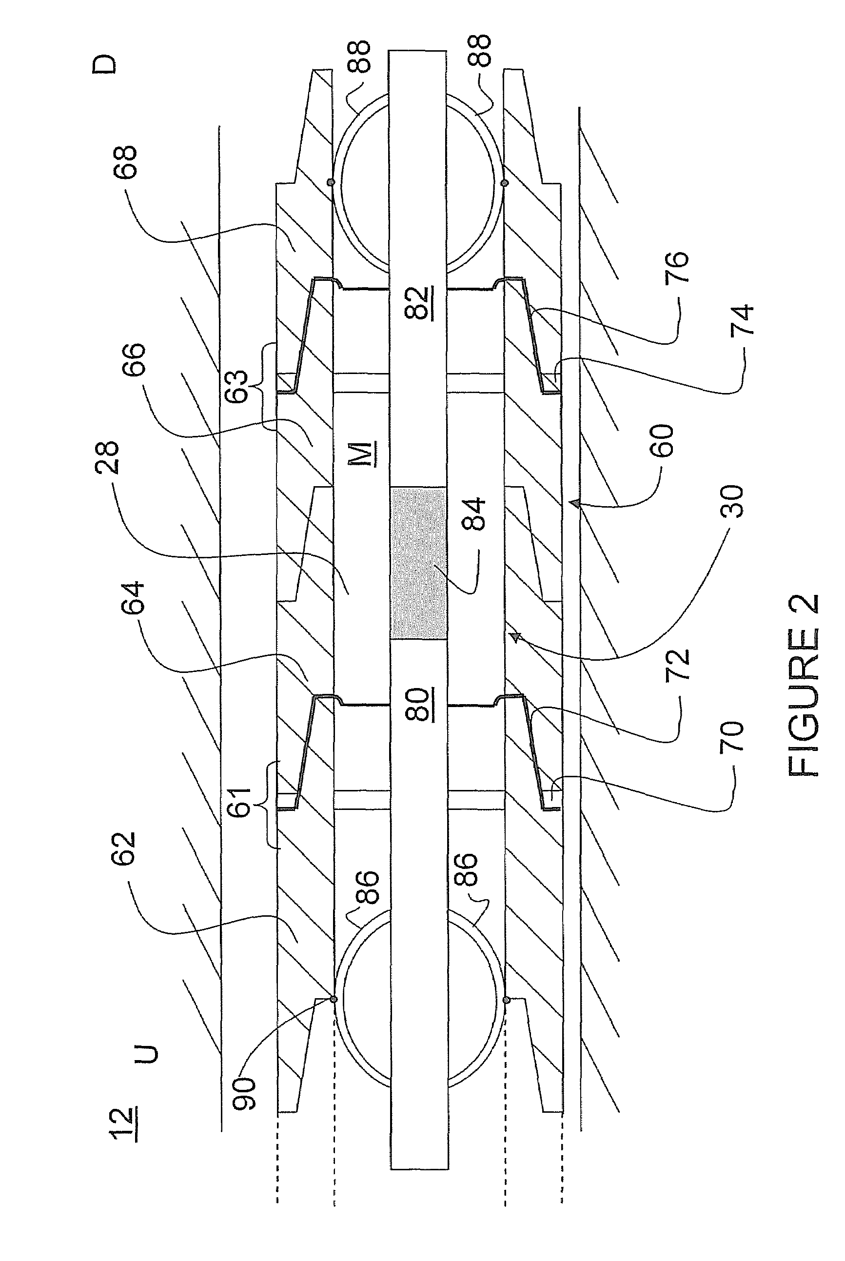
[0045]Referring therefore to FIG. 1, a drilling rig 10 is shown in situ at a drilling site 12. The rig 10 drills a wellbore 14 into an earth formation 16. The wellbore 14 is excavated by operating a drill bit 18 disposed at a lower end 19 of a drill string 20. The drill string 20 is supported at an upper end 21 by drilling equipment 22. As the bit 18 drills into the formation 16, individual drill rods 24, hereinafter referred to as “subs”, are added to the drill string 20 as required. In the example shown in FIG. 1, the drill bit 18 is driven by a fluid motor 26. The fluid motor 26 is powered by the drilling equipment 22 pumping drill fluid, hereinafter referred to as “mud”, using, a mud motor 22a through a hollow conduit 28 (see FIG. 2) defined by interior portions of the connected subs 24. The column of fluid held in the conduit 28 will hereinafter be referred to as a “mud column” and generally denoted by the character “M”.

[0046]An MWD tool 30 is located within...


PUM


Abstract

A system and method are provided for providing electromagnetic (EM) measurement-while-drilling (MWD) telemetry capabilities using an existing mud-pulse MWD tool. An EM tool intercepts the output from the mud-pulse tool and generates an EM signal that mimics a mud-pulse pressure signal. The EM signal is intercepted at the surface by a receiver module that conditions the signal and inputs the signal into the existing pulse tool receiver. Since the EM signal mimics a mud-pulse signal, the pulse tool receiver does not require software or hardware modifications in order to process an EM telemetry mode. The EM tool can be adapted to also provide dual telemetry by incorporating a conventional pressure pulser that would normally be used with the pulse tool. A gap sub assembly for isolating the drill string is also provided that includes a pair of subs whose shoulders are separated by a non-conductive ceramic material and whose threads are separated by an insulative material, preferably a Kevlar™ cloth.

Description

[0001]This application claims priority from Canadian Patent Application No. 2,544,457 filed on Apr. 21, 2006.FIELD OF THE INVENTION[0002]The present invention relates generally to data acquisition during earth drilling operations and telemetry systems therefor, and has particular utility in measurement while drilling (MWD) applications.DESCRIPTION OF THE PRIOR ART[0003]The recovery of subterranean materials such as oil and as typically requires drilling wellbores a great distance beneath the earth's surface towards a repository of the material. The earthen material being drilled is often referred to as “formation”. In addition to drilling equipment situated at the surface, a drill string extends from the equipment to the material formation at the terminal end of the wellbore and includes a drill bit for drilling the wellbore.[0004]The drill bit is rotated and drilling is accomplished by either rotating the drill string or by use of a downhole motor near the drill bit. Drilling fluid...

Claims


Application Information

Patent Timeline
Patent Type & Authority Patents(United States)
IPC IPC(8): G01V3/00E21B47/12E21B47/13E21B47/18
CPCG01V11/002E21B47/18E21B47/122E21B47/12E21B47/017E21B47/13E21B47/22E21B47/24E21B17/003F16L15/08H01B17/20
Inventor PETROVIC, JOHNPETROVIC, VICTORBRAISHER, STEVEN J.
Owner MOSTAR DIRECTIONAL TECH
Why Eureka
Try Eureka