
Apparatus and method for improving the durability of a cooling tube in a fire tube boiler

Inactive Publication Date: 2009-08-18
CITGO GASOLINEEUM CORP
View PDF24 Cites 18 Cited by
  • Summary
  • Abstract
  • Description
  • Claims
  • Application Information

AI Technical Summary

Benefits of technology

[0015]The invention also provides a system for reducing turbulence in a hot fluid entering a cooling tube in a fire tube boiler and improving the operational life of the cooling tube, where the cooling tube has a first tube end inserted through a hole in a first tube sheet of the fire tube boiler for fixed attachment thereto, a second tube end inserted through a hole in a second tube sheet of the fire tube boiler for fixed attachment thereto, and an interior surface with a inner tube diameter that is constant, so that a cooling fluid circulates around the cooling tube. The system comprises a ferrule with a first ferrule end, second ferrule end, and a bore with a bore wall extending therebetween, the second ferrule end inserted within the first tube end, so that the ferrule is disposed to receive a hot fluid entering the first ferrule end and flowing in the direction of the second ferrule end through the bore; and an internal overlay applied as a layer a distance from the first tube end about the interior surface; the layer having a first layer end with an annular inner recess thereabout sized to receive the second ferrule end, a second layer end, and a channel with a channel wall diverging away from the first layer end towards the second layer end, wherein the channel wall at the first layer end is smoothly contiguous with the bore wall at the second ferrule end when the second ferrule end abuts the annular inner recess and when the cooling tube is at an operating temperature.
[0016]A method for reduction of film boiling in a cooling tube is also provided for a cooling with a first tube end, a second tube end, and an interior surface having a constant inner tube diameter. The method comprises the steps of fabricating an internal overlay about the interior surface as a layer that is spaced a distance from the first tube end, the layer having a first layer end with an annular inner recess thereabout, the layer internally diverging from the first layer end to a second layer end to provide a continuous transition from the first layer end to the interior surface; inserting a second ferrule end of a ferrule also with a first ferrule end into the first tube end, the second ferrule end sized to extend from the first tube end to be received in abutting relationship within the annular inner recess at the first layer end, such that a smooth transition is provided between the ferrule and the overlay; providing a cooling fluid about the cooling tube to remove heat therefrom; and allowing a hot fluid to flow from the first tube end to the second tube end through the ferrule and the internal overlay so that heat is removed from the hot fluid through the cooling tube to the cooling fluid. This method thus prevents film boiling of the cooling fluid along a portion of the cooling tube containing the ferrule and the overlay when the cooling tube is at an operating temperature.

Problems solved by technology

The construction of these fire tube boilers has been a source of interest for many engineers, since the high temperatures typically experienced in these processes result in many equipment problems, such as corrosion, deterioration of materials by cracking, compromise of junctions between dissimilar materials, uneven expansion of materials in the equipment, and the like.
Many industrial processes result in the production of hydrogen sulfide (H2S), an odorous, corrosive, and highly toxic gas.
Hydrogen sulfide is generally undesirable because of these qualities and also because it deactivates industrial catalysts.
A catalyst is needed in the second step to help the components react with reasonable speed, but unfortunately the reaction does not go to completion even with the best catalyst.
The high temperatures encountered in such applications, illustrated by the Claus process for example, have resulted in a number of problems for fire tube boilers.
First, when the high temperature gas enters the relatively cool interior of a cooling tube, a phenomenon known as film boiling may occur on the exterior of the tube.
As a result, heat transfer from the tube exterior surface to the water occurs mainly through radiation, which is less efficient than conduction.
Thus, film boiling along tube surface reduces the efficiency of the fire tube boiler and can increase the temperature of the tube wall to a damaging level.
A second common problem with many heat exchanging devices, such as fire tube boilers, is erosion, usually caused by the velocity of flow of the high temperature gas especially adjacent the ends of the tube and over the first few centimeters inside of the tube where the fluid flow may be turbulent.
This problem may be exacerbated by the presence of foreign materials that may be entrained within the gas flow, such as soot or ash in some applications.
A third common problem is corrosion that can be caused by reaction of the gas with the interior surfaces of the tubes.
Furthermore, the junction between the tube and the tube sheet may be vulnerable to such corrosion problems.
A fourth problem that is closely associated with that of corrosion is the exhaustion of ductility of the tube material resulting from extreme swings of temperature within a very short distance.
This repeated heating and cooling may result in cyclic strain accumulation of the tube structure or of the connective structure between the tube and the tube sheet, resulting in cracking, metal fatigue, or other types of damage.
However, the expanded portion of the tube insert presents ridges to an incoming flow of gas, which may cause unwanted turbulence in the gas stream and possible wear.

Method used


Image

  • Apparatus and method for improving the durability of a cooling tube in a fire tube boiler
  • Apparatus and method for improving the durability of a cooling tube in a fire tube boiler
  • Apparatus and method for improving the durability of a cooling tube in a fire tube boiler

Examples


Embodiment Construction

[0021]The following detailed description is of the best currently contemplated modes of carrying out the invention. The description is not to be taken in a limiting sense, but is made merely for the purpose of illustrating the general principles of the invention, since the scope of the invention is best defined by the appended claims.

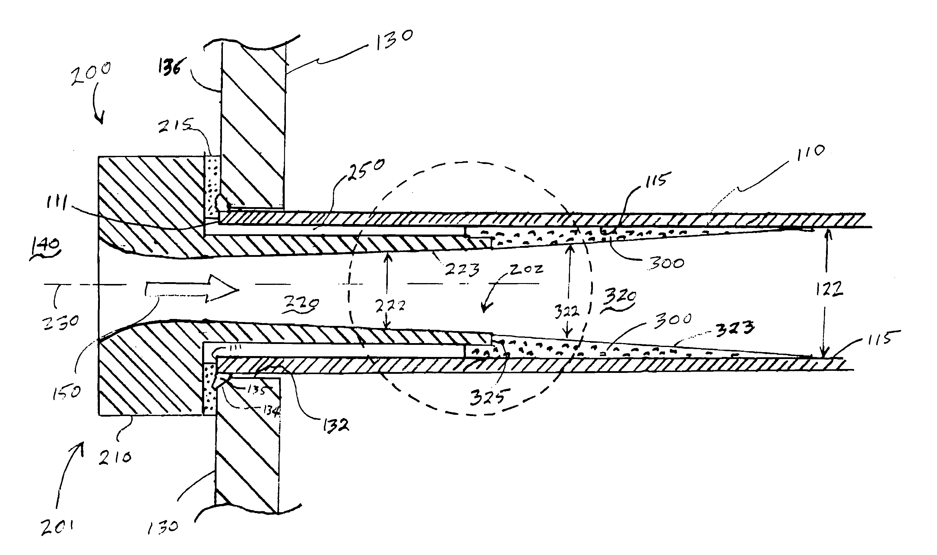
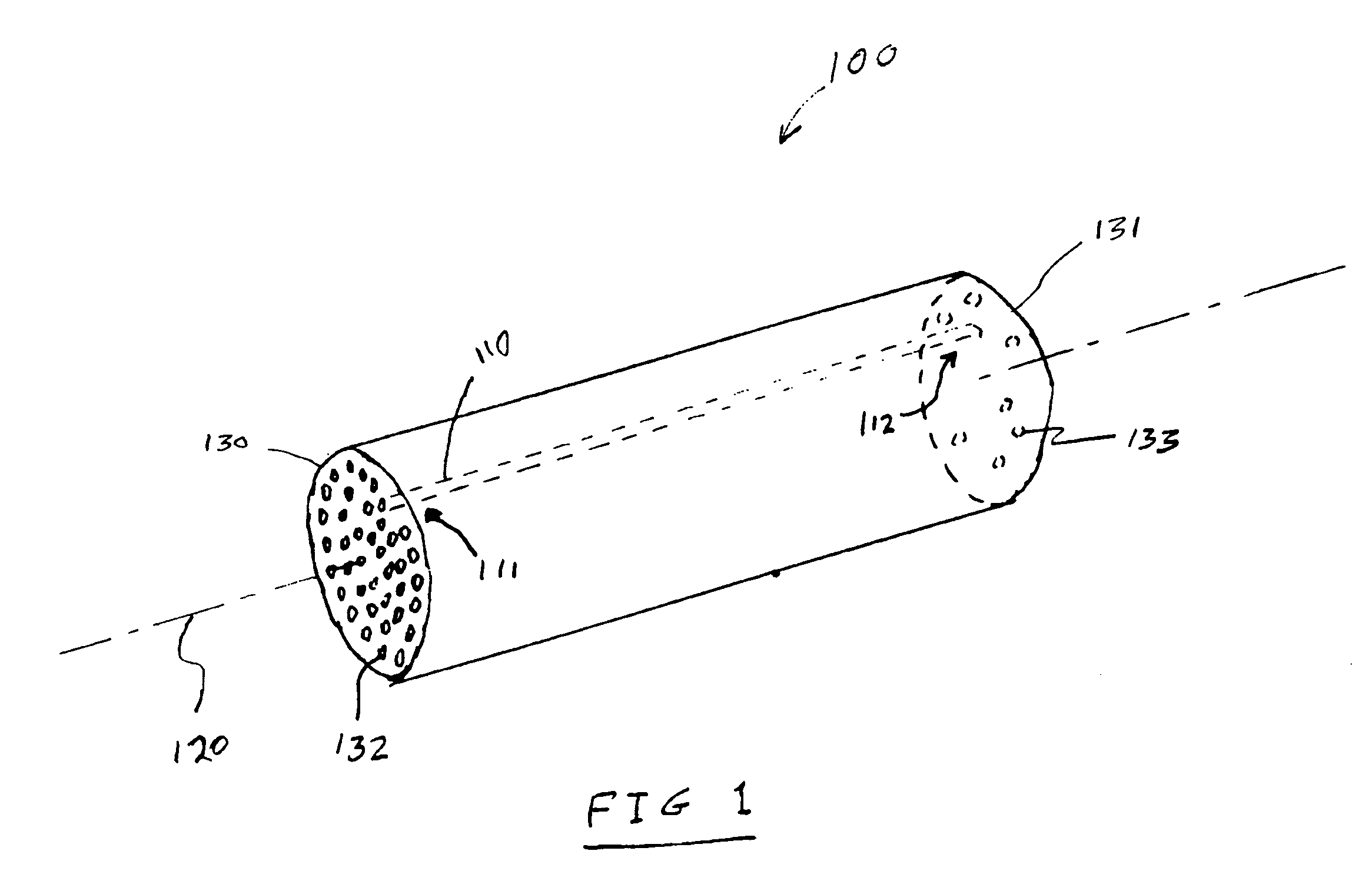
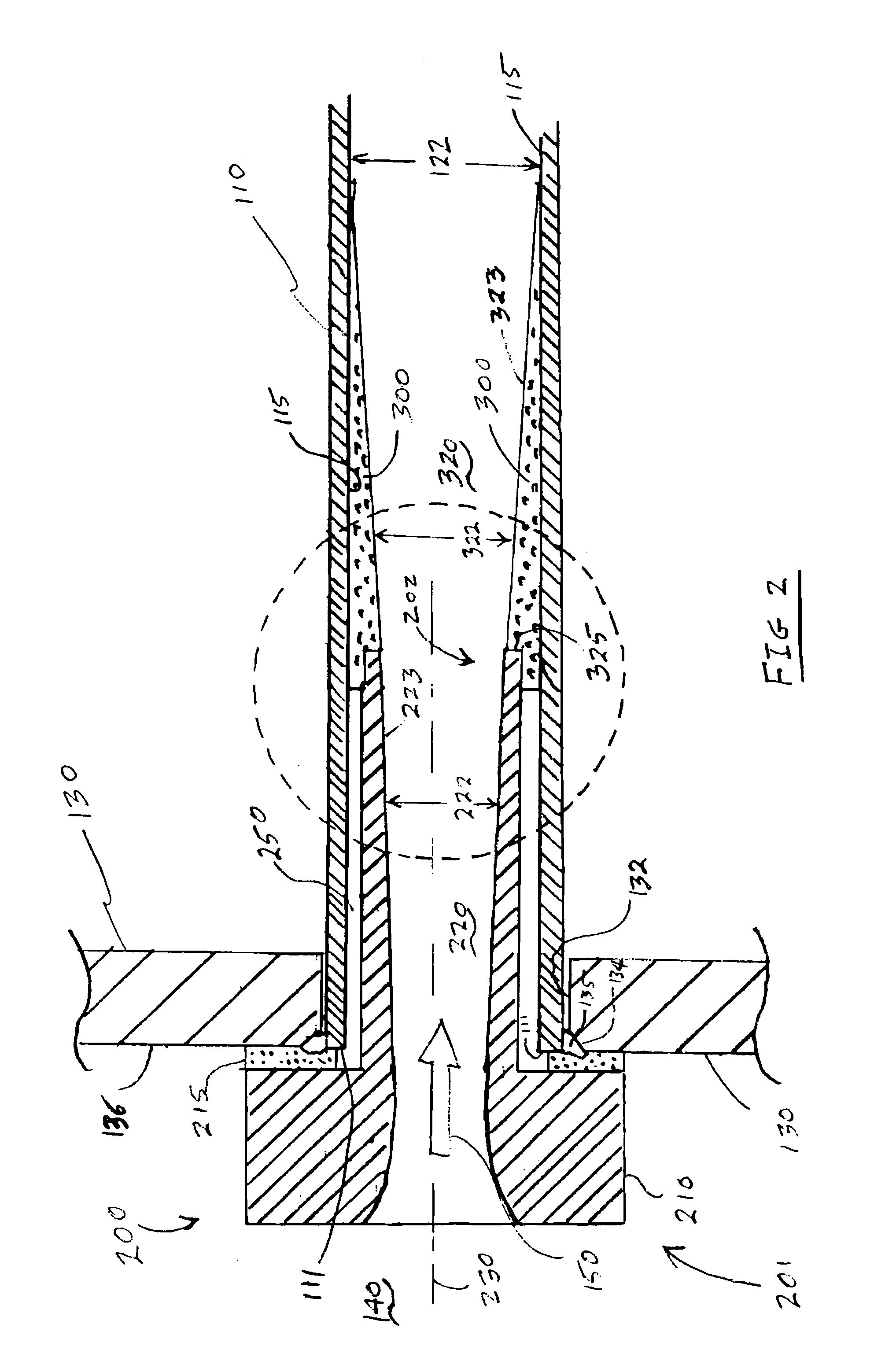
[0022]Broadly, the current invention includes systems, devices, and methods for reducing turbulence within a hot fluid flowing through a cooling tube end and increasing the durability of the cooling tube. The invention includes a cooling tube with an internal, corrosion-resistant overlay positioned proximate the tube end so that it receives an end of a protective ferrule inserted into the tube end. The method of internally applying the internal overlay within the tube end is considered to be unique to the invention. The ferrule and internal overlay may be tapered from the ferrule end to the interior tube wall to provide a smooth flow path and smooth tra...


PUM


Abstract

An apparatus and method for improving the longevity of a cooling tube in a fire tube boiler. The apparatus comprises a ferrule inserted within the cooling tube end and an internal overlay, with the ferrule and internal overlay arranged to provide a smooth, continuous, and diverging passage that reduces turbulence for a heated fluid flowing therethrough, thus preventing the overheating of the tube wall in the highly turbulent area. The internal overlay may be a weld overlay of a corrosion-resistant material that is deposited in a band about the inner wall of the cooling tube, the overlay having an annular inner recess receiving the end of the ferrule. The combination of ferrule and internal overlay also reduces the sharp gradient in temperature that is encountered when the heated fluid enters the relatively cool tube end, thus reducing film boiling, reducing cracking of the tube end, and enhancing corrosion resistance.

Description

BACKGROUND OF THE INVENTION[0001]The present invention generally relates to methods and devices for cooling fluids, and more particularly to the construction and configuration of fire tube boilers and water tube boilers, and still more particularly to increasing the durability of cooling tubes used in such devices.[0002]Many industrial processes employ high temperature heat exchangers, sometimes called fire tube boilers or water tube boilers, to remove heat from a fluid stream, either a gas or a liquid. The construction of these fire tube boilers has been a source of interest for many engineers, since the high temperatures typically experienced in these processes result in many equipment problems, such as corrosion, deterioration of materials by cracking, compromise of junctions between dissimilar materials, uneven expansion of materials in the equipment, and the like. Illustrative of these problems are processes that involve the removal of hydrogen sulfide gas from certain industri...

Claims


Application Information

Patent Timeline
IPC IPC(8): F28F19/00
CPCF28F19/002F28D7/16
Inventor SCHULZ, CLINTON J.
Owner CITGO GASOLINEEUM CORP
Features
  • Generate Ideas
  • Intellectual Property
  • Life Sciences
  • Materials
  • Tech Scout
  • Unparalleled Data Quality
  • Higher Quality Content
  • 60% Fewer Hallucinations
Learn More