Temperature/humidity exchanger

a technology of temperature/humidity exchanger and exchanger, which is applied in the direction of fuel cell details, trickle coolers, machines/engines, etc., can solve the problems of extra cost, achieve the effect of reducing the dew point of the output gas, improving temperature efficiency and humidity efficiency, and restricting pressure loss

Inactive Publication Date: 2009-09-08
MITSUBISHI ELECTRIC CORP
View PDF21 Cites 21 Cited by
  • Summary
  • Abstract
  • Description
  • Claims
  • Application Information

AI Technical Summary

Benefits of technology

[0016]An effect of the temperature-humidity exchanger according to the present invention is that the temperature efficiency and the humidity efficiency are improved by flowing the same gas in the channel grooves divided by half in a stacking direction, thereby making it possible to raise the dew point of the output gas. Further, even if the depth of the channel grooves is decreased, both of the channel grooves regarded to have a double depth and an aggregate communication groove which aggregates the plural channel grooves are made to communicate with each other, so a spot where a hydraulic equivalent diameter of the channel through which the gas is caused to flow becomes extremely small is not found, thereby making it possible to restrict the pressure loss to the allowable pressure loss or less.

Problems solved by technology

However, a water supply device which prepares water heated as humidification water is separately required, resulting in extra cost.

Method used


Image

  • Temperature/humidity exchanger
  • Temperature/humidity exchanger
  • Temperature/humidity exchanger

Examples


embodiment 1

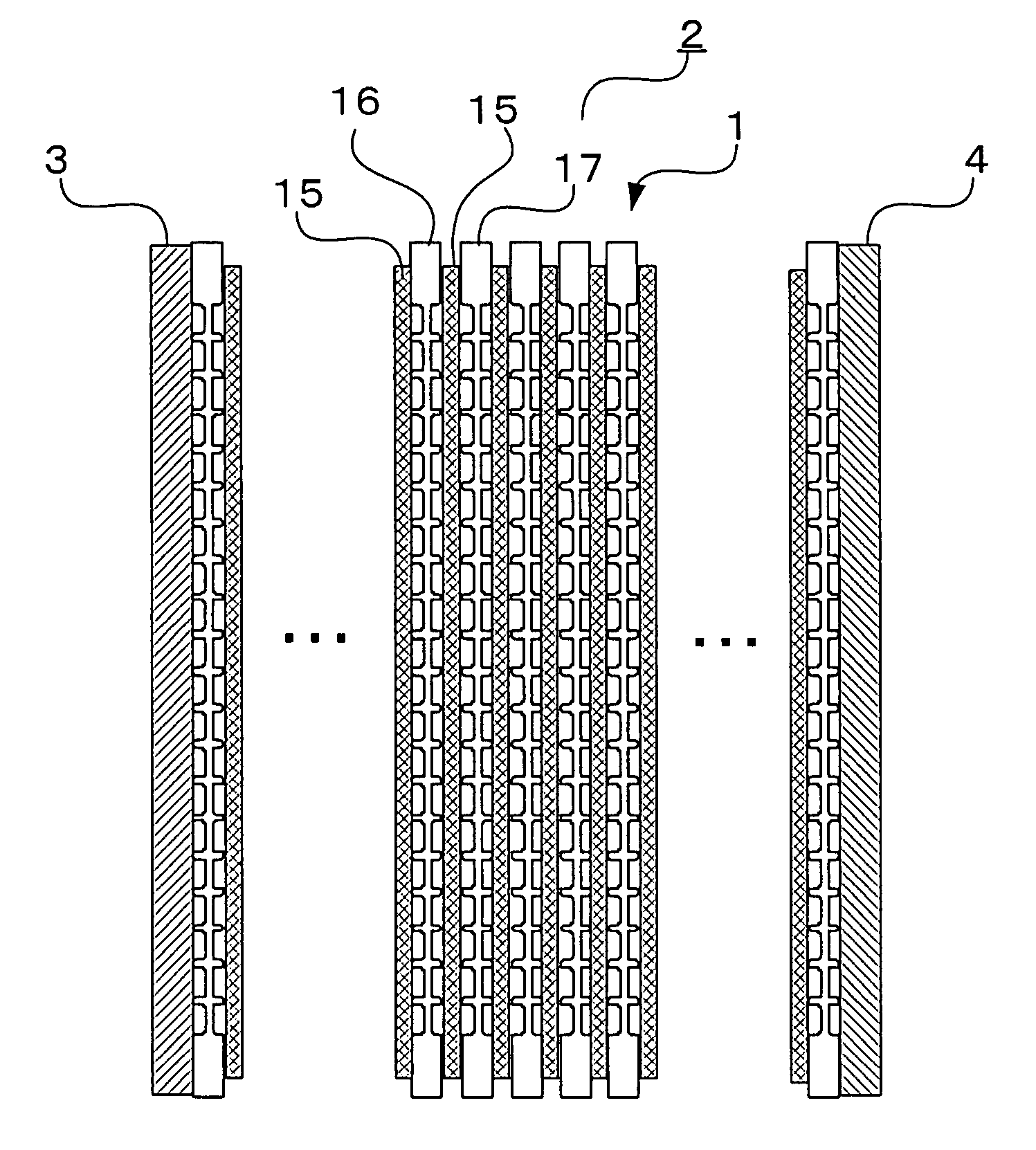
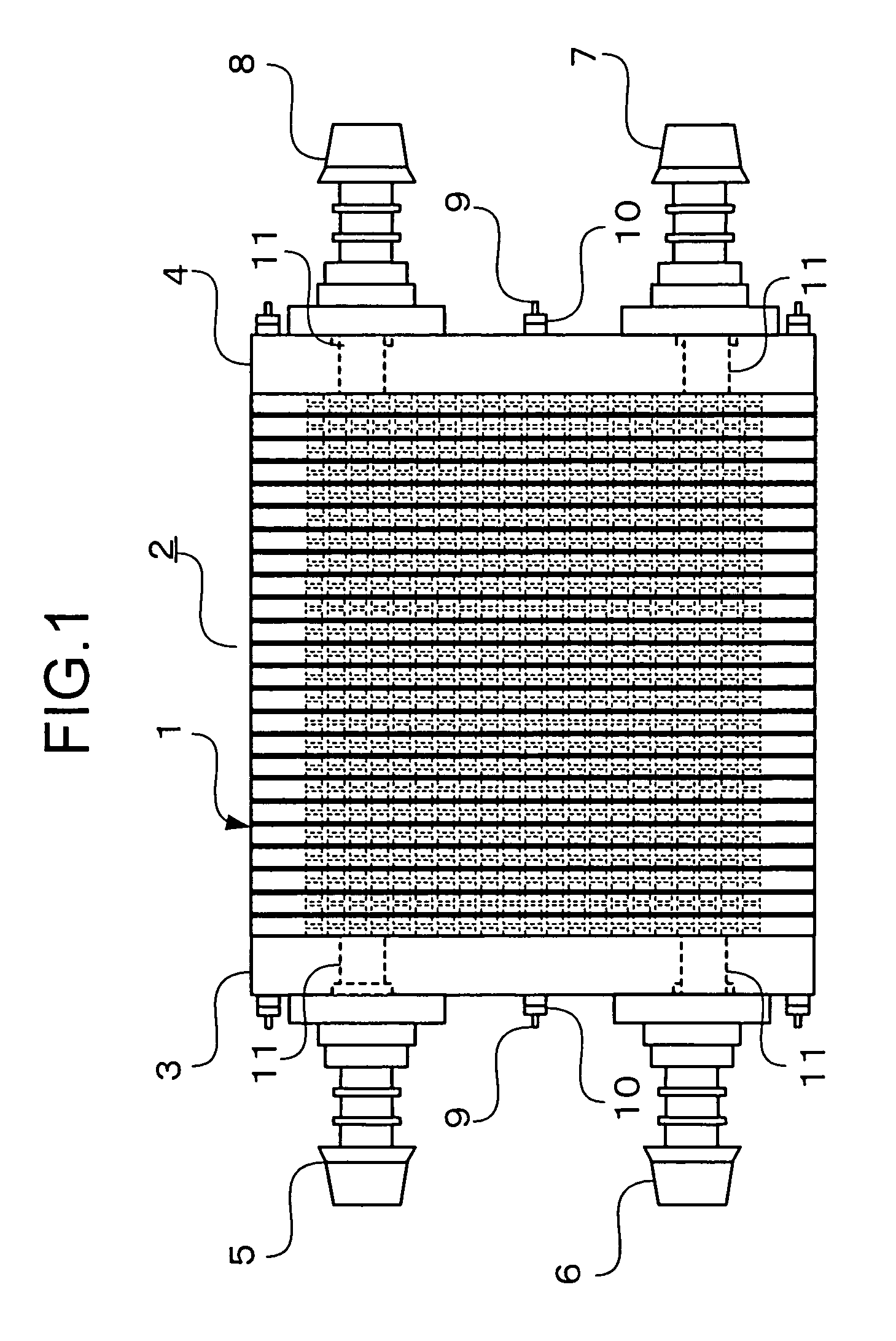
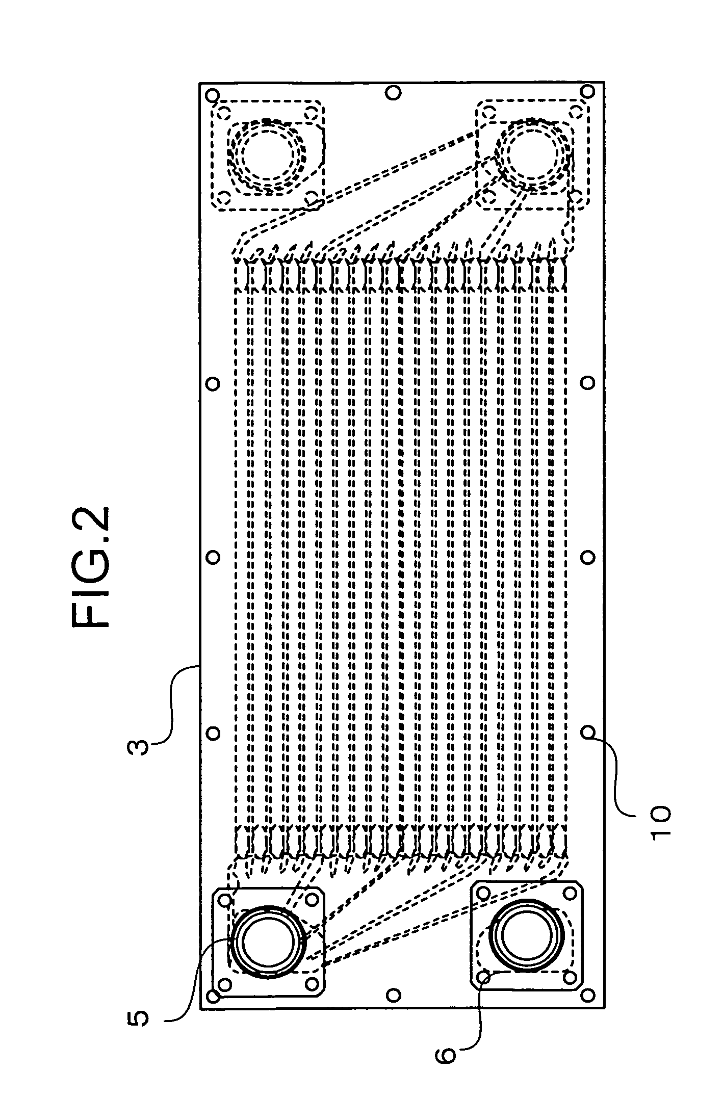
[0029]FIG. 1 is a side view of a temperature-humidity exchanger according to Embodiment 1 of the present invention. FIG. 2 is an upper plan view of the temperature-humidity exchanger of Embodiment 1. FIG. 3 is a partial cross-sectional view of temperature-humidity exchange cells. FIG. 4 is a plan view of a dry gas separator of the temperature-humidity exchange cell. Note that, in the following description, dry gas is described as air in which temperature is approximately room temperature and relative humidity is approximately zero. Further, wet gas is described as oxidizer outlet gas of a polymer electrolyte fuel cell, for example, in which temperature is 70° C. or more and relative humidity is 90% or more.

[0030]As shown in FIGS. 1 and 2, a temperature-humidity exchanger of Embodiment 1 includes a temperature-humidity exchange stacked body 2 in which a plurality of temperature-humidity exchange cells 1 are stacked, an inlet retainer plate 3 and an outlet retainer plate 4 which sandw...

embodiment 2

[0071]FIG. 10 is an upper plan view of a temperature-humidity exchanger of Embodiment 2 of the present invention. FIG. 11 is a plan view of a dry gas separator of a temperature-humidity exchange cell according to Embodiment 2.

[0072]The temperature-humidity exchanger according to Embodiment 2 is different from the temperature-humidity exchanger according to Embodiment 1 in positions of the dry gas inlet manifold 5, the dry gas outlet manifold 7, the wet gas inlet manifold 8, and the wet gas outlet manifold 6, and is the same thereto in other constructions. Accordingly, a description of the same portions is omitted.

[0073]As shown in FIG. 10, the dry gas inlet manifold 5 and dry gas outlet manifold 7 of the temperature-humidity exchanger according to Embodiment 2 are provided at positions axisymmetric to each other with respect to a long-side center line.

[0074]In the dry gas separator 16 of Embodiment 1, the dry gas supply manifold 35 and the dry gas exhaust manifold 36 are provided at...

embodiment 3

[0080]FIG. 12 is a side view of a temperature-humidity exchanger according to Embodiment 3 of the present invention. The temperature-humidity exchanger according to Embodiment 3 is different from that of Embodiment 1 in that the temperature-humidity exchange stacked body of Embodiment 1 is divided by half, and that a direction in which the dry gas is caused to flow in one of the temperature-humidity exchange stacked bodies is reverse to a direction in which the dry gas is caused to flow in the other temperature-humidity exchange stacked body. The other constructions are the same as those of Embodiment 1, so a description of the same portions is omitted.

[0081]As shown in FIG. 12, in the temperature-humidity exchanger of Embodiment 3, two temperature-humidity exchange stacked bodies on the upper and lower sides 41a and 41b are sandwiched by the inlet retainer plate 3 and the outlet retainer plate 4. Between a lowermost dry gas separator 42 of the temperature-humidity exchange stacked ...


PUM

PropertyMeasurementUnit
pressure lossaaaaaaaaaa
temperatureaaaaaaaaaa
thicknessaaaaaaaaaa

Abstract

A temperature-humidity exchanger comprising: a moisture permeable membrane which transmits moisture therethrough; a dry gas separator in which low-temperature dry gas is caused to flow; and a wet gas separator in which high-temperature wet gas is caused to flow, in which the moisture permeable membrane, the dry gas separator, the moisture permeable membrane, and the wet gas separator are repeatedly stacked in the stated order, wherein in the dry gas separator and the wet gas separator: a plurality of channel grooves which are divided by half in the stacking direction, are open to a direction in which the channel grooves come into contact with the moisture permeable membrane, and are arrayed parallel to one another are provided; an aggregate communication groove which is made to communicate with both end portions of the plurality of channel grooves, for aggregating gas caused to flow through the channel grooves to at least one is provided; and a supply manifold and an exhaust manifold which are made to communicate with the aggregate communication groove and penetrate the separators in the stacking direction are provided; and a flow of the dry gas caused to flow in the channel grooves of the dry gas separators and a flow of the wet gas caused to flow in the channel grooves of the wet gas separators are counterflows.

Description

TECHNICAL FIELD[0001]The present invention relates to a temperature-humidity exchanger for heating and humidifying low-temperature dry gas by heat and moisture, which are transmitted, through a moisture permeable membrane through which the moisture is transmitted, from high-temperature wet gas, and particularly, to a temperature-humidity exchanger for a fuel cell, for heating and humidifying unreacted gas by heat and moisture, which are transmitted from exhaust gas of the fuel cell.BACKGROUND ART[0002]In a polymer electrolyte fuel cell, an ion exchange membrane has exchange groups for hydrogen ions in molecules thereof, and functions as an ion conductive substance by being saturated and hydrous. Then, when the ion exchange membrane is dried, ion conductivity thereof decreases, and cell performance of the fuel cell significantly decreases. Accordingly, in order to prevent the ion exchange membrane from being dried, unreacted gas is humidified in advance by using a temperature-humidit...

Claims


Application Information

Patent Timeline
Patent Type & Authority Patents(United States)
IPC IPC(8): B01D53/22F28D5/00F28F3/08H01M8/02
CPCF28F3/083H01M8/04074H01M8/04149Y02E60/50H01M8/04141
Inventor GONJO, YOSHIHIDEICHIMURA, HIDEOMATSUMURA, MITSUIE
Owner MITSUBISHI ELECTRIC CORP
Why Eureka
Try Eureka