Power plant and fuel supply method therefor

a technology for power plants and fuel supply devices, which is applied in the direction of machines/engines, combustion air/fuel air treatment, electric control, etc., can solve the problems of increasing unburnt hc (hydrocarbons) and pm (particle materials), and the inability to reform all fuel components, so as to achieve suppressed undesired fuel flow on the walls and high boiling point

Inactive Publication Date: 2009-09-15
NISSAN MOTOR CO LTD
View PDF3 Cites 22 Cited by
  • Summary
  • Abstract
  • Description
  • Claims
  • Application Information

AI Technical Summary

Benefits of technology

[0009]According to the present invention, by using only one fuel conversion device, both an evaporated fuel and a reformed fuel are produced, and the fuel supplied from the outside is fed to the internal combustion engine as the evaporated fuel, and thus, even if the fuel supplied from the outside is a fuel such as light oil or the like that has a relatively high boiling point, the undesired fuel flow on walls is suppressed.

Problems solved by technology

However, when the original fuel is a fuel (for example, gasoline) that is available on the market, it is impossible to reform all of the fuel components, and thus, it is necessary to also feed the engine with the original fuel for combustion in the engine.
However, in case of using a fuel (for example, light oil or the like) that has a relatively high boiling point as the original fuel, undesired fuel flow on the walls of intake ports and combustion chambers tends to occur which causes the problem of increased unburnt HC (Hydrocarbons) and PM (Particle Materials).

Method used


Image

  • Power plant and fuel supply method therefor
  • Power plant and fuel supply method therefor
  • Power plant and fuel supply method therefor

Examples


first embodiment

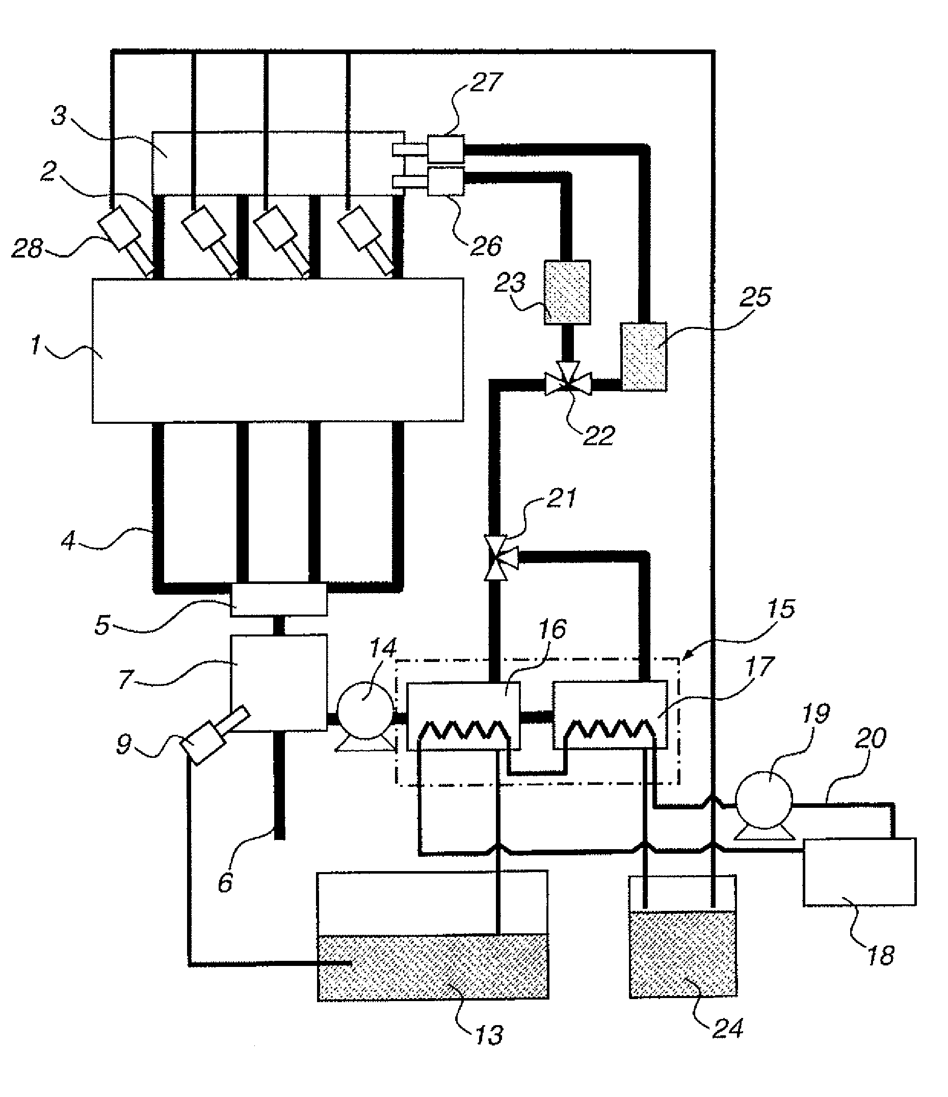
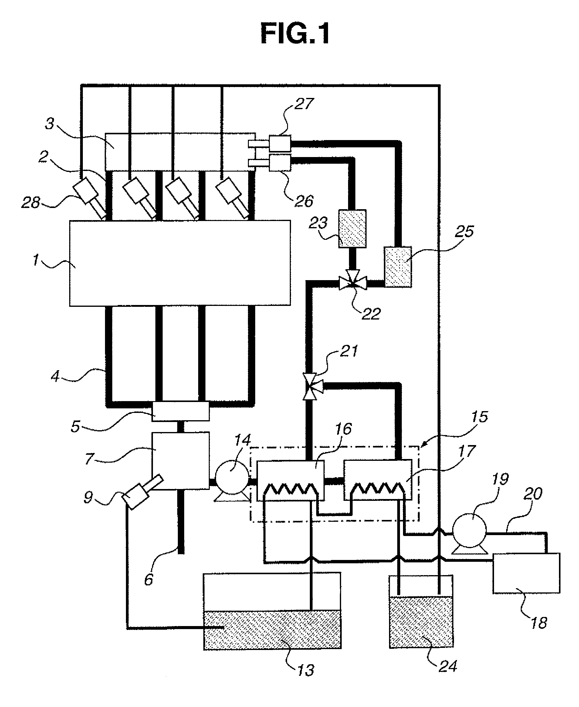
[0024]FIG. 1 is a block diagram showing a power plant of the present invention. In FIG. 1, an engine 1 is connected to an intake collector 3 through an intake manifold 2. An exhaust purifying catalyst 5 is connected to a branch joined portion of an exhaust manifold 4 of engine 1. Around an exhaust pipe 6 that extends downward from the catalyst, there is mounted a fuel conversion device 7 that converts a supplied liquid fuel to an evaporated fuel and a reformed fuel by practically using waste heat of the internal combustion engine as energy, such as waste heat from exhaust pipe 6.

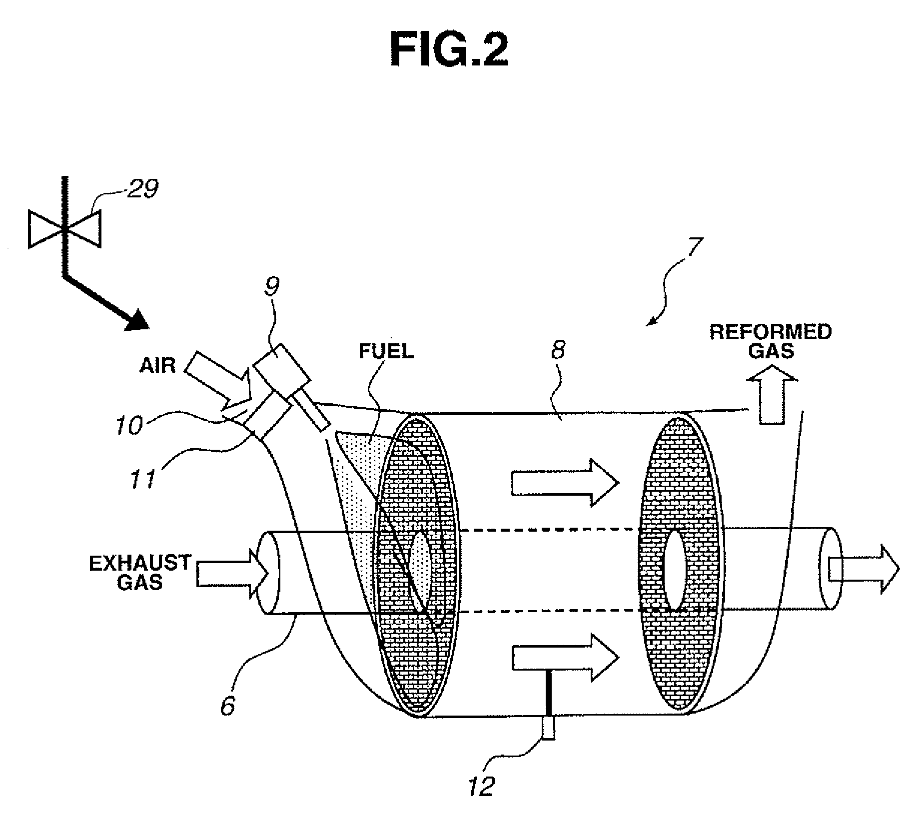
[0025]Details of fuel conversion device 7 are shown in FIG. 2. In fuel conversion device 7, there is formed a cylindrical space that surrounds exhaust pipe 6, and in the space, there is arranged a reforming catalyst 8 that includes a honeycomb cordierite bed coated with platinum catalyst. At an inlet side of reforming catalyst 8, there is provided an air intake opening 10 through which air can enter device 7...

second embodiment

[0072]FIGS. 11 and 12 show fuel supply control maps provided in accordance with an operation condition of the

[0073]In the second embodiment, like in the first embodiment, a low octane fuel with a high boiling point is fed to engine 1 after being changed to an evaporated fuel, and thus, even when a fuel having a high boiling point, like light oil or the like, is used, undesirable fuel flow on walls of the intake port and combustion chamber is suppressed or at least minimized. Furthermore, only when the engine is under a low load operation condition, the reformed gaseous fuel is fed to auxiliary combustion chamber 41 to produce jetted flame through nozzle holes 42 the for burning the mixture of the evaporated fuel and air in main combustion chamber 35. Accordingly, the combustion stability of the mixture in combustion chamber 35 under the low load operation condition is much improved as compared with that of the above-mentioned first embodiment. Thus, the lean limit for stable combust...


PUM


Abstract

A power plant, including an internal combustion engine, a fuel conversion device that coverts a fuel to be supplied to the internal combustion engine from a before-conversion fuel to an after-conversion fuel, a first fuel supply device that supplies the fuel conversion device with the before-conversion fuel, a second fuel supply device that supplies the internal combustion engine with the after-conversion fuel, the after-conversion fuel being the fuel that has been converted by the fuel conversion device, and a controller that is communicated with the internal combustion engine, the fuel conversion device, the first fuel supply device and the second fuel supply device. The controller is configured to supply the fuel conversion device with the before-conversion fuel by operating the first fuel supply device, control the temperature of the fuel conversion device in a first temperature range to evaporate the before-conversion fuel to produce a first after-conversion fuel, control the temperature of the fuel conversion device in a second temperature range to reform the before-conversion fuel to produce a second after-conversion fuel, and supply the internal combustion engine with the after-conversion fuel by operating the second fuel supply device.

Description

CROSS-REFERENCE TO RELATED APPLICATIONS[0001]This application claims priority under 35 U.S.C. § 119 to Japanese Patent Application No. 2007-111129, filed on Apr. 20, 2007, which is incorporated by reference herein in the entirety.BACKGROUND OF THE INVENTION[0002]1. Field of the Invention[0003]The present invention relates to a fuel supply device that feeds an internal combustion engine with a fuel, and more particularly to a fuel supply device for an internal combustion engine that is equipped with a fuel conversion device.[0004]2. Description of Related Art[0005]In the related art, there has been proposed an internal combustion engine in which an in-tank fuel (such as cyclohexane or the like, that is a before-convention fuel led into a fuel tank from the outside) is reformed into hydrogen and a high-octane fuel (e.g. having a benzene nucleus) by a dehydrogen-reforming reaction. Such hydrogen and high-octane fuel are fed to the engine to combust in the engine, such that a low load f...

Claims


Application Information

Patent Timeline
Patent Type & Authority Patents(United States)
IPC IPC(8): F02B43/08F02G5/00
CPCC01B3/26F02D19/0692F01N5/02F02D19/0605F02D19/081F02D41/0025F02M25/12F02M27/02F02M31/093F02D19/0644F02D19/0665F02D19/0671F02D19/0676C01B3/386C01B2203/0261C01B2203/0277C01B2203/0811C01B2203/1023C01B2203/107C01B2203/1247C01B2203/1288C01B2203/1604C01B2203/1619C01B2203/169F01N2240/30Y02T10/36Y02T10/126Y02T10/16Y02T10/12Y02T10/30Y02P20/129
Inventor HOTTA, ISAMUMINAMI, YUTARO
Owner NISSAN MOTOR CO LTD
Why Eureka
Try Eureka